T606MSx-4 and T606MSx-4+PIR Series Multi-Stage Temperature and Humidity Controllers
Installation Instructions
4
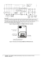
Figure 6: Wiring the T606MSx-4 or T606MSx-4+PIR Series Controller
Cool 2
24 VAC
Thermostat Controller
Power
Y2
Y1
G
RC
C
Heat 1 Heat 2
RH
W1
W2
Fan
Cool 1
Scom
HS
DI
0–10 VDC
Remote
Room
Humidity
Sensor
OS
Outdoor
Air
Temperature
Sensor
HUM
0 to 10
VD
C
24 V
A
C
Co
m
m
o
n
Aux
AUX
0–10 VDC
High Limit
Humidity
Sensor
Cool 2
F
IG:
T6
0
6
MS
x
_
wi
r
Independent Contact
- Lighting
- On/Off Actuation
- Exhaust Fan
DE
HUM
Dehum
Output
Wiring Notes:
1. If you use the same power source for the heating stages, install a jumper across RC and RH. Maximum current is 2.0 amperes.
2. If you use the auxiliary output to toggle occupancy of the electronic control card inside the equipment, configure the relay
parameter (Aux Cont) to the Normally Open (N.O.) setting. A second relay can be added for additional occupancy input functions.
3. The humidifier output uses a half-bridge rectifier. The control signal reference is the controller power supply common (terminal C).
4. Electromechanical contacts are used with the digital input. Electronic triacs cannot be used for input switching. Use
terminal C (common) for the switching leg of the digital input.
5. The unit transformer provides power to the controller and the additional loads that are wired to the controller.
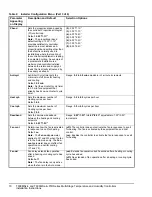
Figure 7: Front Cover of Controller (T606MSx-4+PIR Model Shown)
Backlit, plain text
LCD is easy to read
in any condition.
Five keys on the thermostat controller
make operation easy and intuitive.
LEDs indicate
system activity.
F
IG
:f
rnt
_v
w
PIR motion detector
saves energy.
27.0 %RH
70.0 °F


