VYPER
™
VARIABLE SPEED DRIVE
MAINTENANCE
S100-200 IOM (MAY 08)
Page 56
Fault 52: Harmonic Filter High Phase B Current
Message
Quantum: “Fault 52”
Quantum LX: “ Harmonic Filter High Phase B Current Fault”
Same as Fault 51 except for applying to Phase B.
Fault 53: Harmonic Filter High Phase A Current
Message
Quantum: “Fault 53”
Quantum LX: “ Harmonic Filter High Phase A Current Fault”
Same as Fault 51 except for applying to Phase B.
Fault 54: Harmonic Filter Phase Locked Loop
Message
Quantum: “Fault 54”
Quantum LX: “ Harmonic Filter Phase Locked Loop Fault”
This shutdown indicates that a circuit called a “phase locked
loop” on the Filter Logic board has lost synchronization with
the incoming power line for a period of time. This is normally
an indication that one of the Filter’s incoming power fuses is
blown. Check fi lter power fuses 8FU, 9FU and 10FU if this
shutdown occurs. If the fuses are OK, then check the output of
the line voltage isolation board at connector J5, pins 1, 2, and 3
on the Filter logic board. With 480 VAC present on the input to
the line voltage isolation board, approximately 5.2 VAC should
be present from pins 1 to 2, pins 2 to 3, and pins 3 to 1.
Fault 56: Harmonic Filter Logic Board Power Supply
Message
Quantum: “Fault 56”
Quantum LX: “ Harmonic Filter Logic Board Power Supply”
This shutdown indicates that one of the low voltage power
supplies on the Filter Logic board have dropped below their
permissible operating voltage range. The fi lter logic board
receives its power from the Vyper
™
Logic board via the rib-
bon cable which connects the two. The power supplies for
the logic boards are in turn derived from the secondary of the
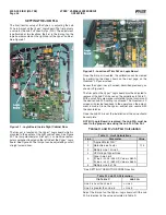
120 to 24 VAC transformer (Figure 7a) which in turn is derived
from the 480 to 120 VAC control transformer (Figure 7). If
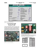
this shutdown occurs, check the CR10 LED, labeled “Power
Supply OK”. If this is not illuminated, check the ribbon cable
connecting the fi lter logic board to the Vyper
™
logic board.
If the CR10 LED is illuminated, there is a faulty fi lter logic
board, which needs to be replaced.
Fault 65: Harmonic Filter Precharge High DC Bus Voltage
Message
Quantum: “Fault 56”
Quantum LX: “ Harmonic Filter Logic Board Power Supply”
The DC link voltage will reach at least 525 VDC within 5
seconds after the precharge relay is pulled in on the 60 Hz
519 fi lter and at least 425 VDC within 5 seconds on the 50
Hz 519 fi lter. If not, the Quantum
™
LX panel will display the
message Fault 65.
Fault 66: Harmonic Filter Precharge Low DC Bus Voltage
Message
Quantum: “Fault 66”
Quantum LX: “ Harmonic Filter Precharge Low DC Bus Voltage”
The DC link voltage will reach at least 50 VDC within 100
msec after the precharge relay has been pulled in on the 60
Hz 519 fi lter and at least 41 VDC within 100 msec on the 50
Hz 519 fi lter. If not, the Quantum
™
LX panel will display the
message Fault 66.
This shutdown requires that two minimum voltage thresholds
must be exceeded in order to complete precharge. During
precharge the fi lter’s DC bus voltage must be equal to or
greater than 50 VDC (41 VDC for 50 HZ) 1/10 second after
the fi lter precharge relay is energized. Also, the fi lter’s DC
bus voltage must be equal to or greater than 525 VDC (425
VDC for 50 HZ) within 5 seconds after the fi lter precharge
relay is energized. The unit is shut down, and this message is
generated if this condition is not met. If this shutdown occurs,
check the fi lter precharge relay, fi lter precharge resistors,
and the wiring between the fi lter logic board and the fi lter
precharge relay.
Fault 67: Harmonic Filter DC Current Transformer 1
Message
Quantum: “Fault 67”
Quantum LX: “ Harmonic Filter DC Current Transformer 1”
During initialization the output voltage of the two DCCT’s
which sense the fi lter’s input current will be monitored and
compared against a level of ± 147 mv (± 6010 A to D counts).
If the offset error falls outside this range, the unit will trip and
the Quantum
™
LX panel will display the message Fault 67. If
a DCCT error fault is not encountered, an average of eight
readings on each DCCT output will be taken and used for
DCCT offset compensation. The three phases of VSD input
current are sensed by two current transformers. The three
phases of fi lter input current are sensed by two D.C. current
transformers. The third fi lter input current is derived from the
equation I
f2
= -I
f1
–I
f3
.
Fault 68: Harmonic Filter DC Current Transformer 2
Message
Quantum: “Fault 68”
Quantum LX: “ Harmonic Filter DC Current Transformer 2”
Same as Fault 67 except applying to Harmonic Filter DC
Current transformer 2.
Fault 69: Harmonic Filter High Base plate Temperature
Message
Quantum: “ Fault 69“
Quantum LX: “ Harmonic Filter High Base plate Temp Fault”
The unit contains one heatsink assembly for the 305 Hp. The
Filter’s power module base plate temperature (see Appendix
I for thermistor temperature vs. A to D count) will feed plug
J6 on the Harmonic Filter Logic board. This temperature is
compared in software to a limit of 79°C and if this limit is
exceeded, the unit will trip and the Quantum
™
LX
panel will
display the message Fault 69.
A thermistor sensor is located inside the IGBT Module on
the fi lter power unit. If at anytime this thermistor detects a
temperature of 175°F (79°C) or higher a shutdown will occur.
A manual reset is required by pressing the “Overtemp Reset”
push button located on the Filter Logic board. This message
is usually an indication that the level of coolant in the closed-
loop system on the back of the Vyper
™
is low.
Fault 71: Harmonic Filter Low DC Bus Voltage
Message
Quantum: “Fault 71”
Quantum LX: “ Harmonic Filter Low DC Bus Voltage”
Содержание Frick vyper VYA PG -46
Страница 15: ...VYPER VARIABLE SPEED DRIVE INSTALLATION S100 200 IOM MAY 08 Page 15 Liquid Cooled Vyper P I Diagram Economized ...
Страница 24: ...VYPER VARIABLE SPEED DRIVE INSTALLATION S100 200 IOM MAY 08 Page 24 ANALOG BOARD WIRING Figure 21 ...
Страница 62: ...S100 200 IOM MAY 08 Page 62 VYPER VARIABLE SPEED DRIVE NOTES ...
Страница 63: ...S100 200 IOM MAY 08 Page 63 VYPER VARIABLE SPEED DRIVE NOTES ...

