VYPER
™
VARIABLE SPEED DRIVE
OPERATION
S100-200 IOM (MAY 08)
Page 45
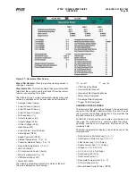
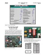
Figure 53 - Vyper
™
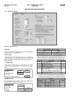
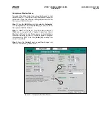
Level 2 Screen
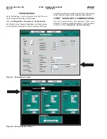
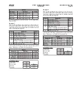
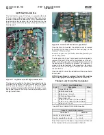
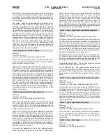
Figure 55 - Dip Switch Settings
The
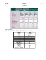
FIB Switch Status Chart
table shows the proper dip
switch settings. Please verify that the switches are set to
these positions before attempting to start the unit.
FIB Switch Status Chart
Switch Status
Switch Status
4
Open
8
Open
3
Open
7
Closed
2
Closed
6
Open
1
Closed
5
Open
4
Open
3
Open
Open
2
Open
1
Open
FRICK INTERFACE BOARD
DIP SWITCH SETTINGS
(Used before Jan 2008)
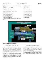
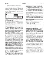
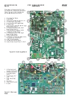
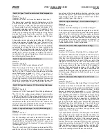
On the Frick Interface Board (Figure 54) on the Vyper
™
right
door there is a dip switch array. The array is located at the
upper right of the FIB as shown in the photograph below.
This dip switch array must be set correctly for the Vyper
™
to
operate properly. The switches should be set at the factory
but it is good practice to verify the settings before starting the
Vyper
™
. The switches should be set as shown in Figure 55.
Figure 54 - Frick Interface Board
Содержание Frick vyper VYA PG -46
Страница 15: ...VYPER VARIABLE SPEED DRIVE INSTALLATION S100 200 IOM MAY 08 Page 15 Liquid Cooled Vyper P I Diagram Economized ...
Страница 24: ...VYPER VARIABLE SPEED DRIVE INSTALLATION S100 200 IOM MAY 08 Page 24 ANALOG BOARD WIRING Figure 21 ...
Страница 62: ...S100 200 IOM MAY 08 Page 62 VYPER VARIABLE SPEED DRIVE NOTES ...
Страница 63: ...S100 200 IOM MAY 08 Page 63 VYPER VARIABLE SPEED DRIVE NOTES ...

