VYPER
™
VARIABLE SPEED DRIVE
MAINTENANCE
S100-200 IOM (MAY 08)
Page 49
When is a booster pump required on a Vyper
™
compres-
sor drive?
The Frick Vyper
™
requires 8 ft of head for proper coolant fl ow
(water or glycol) to the heat exchanger. If this amount of head
is not available, then a booster pump is required.
The pink color of the coolant has faded. Is there a prob-
lem?
The coolant normally has a pink or rosy color when new. After
months of operation, this color may dissipate, and the coolant
may appear almost colorless. The lack of color in the cool-
ant does not necessarily indicate a problem. Most colorless
samples test above 1000 PPM nitrite, which is normal. There
is no need to fl ush the system unless the coolant becomes
opaque or cloudy. If this is the case, please obtain a sample
for analysis, then fl ush the system with coolant and install
fresh coolant. Be aware that cloudy coolant may contain
bacteria. Please use adequate preventative procedures to
avoid contamination. The coolant must be charged every
year regardless of color.
Why is the Vyper
™
circuit breaker tripping?
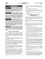
Circuit breaker tripping is normal for a failed Vyper
™
drive.
The unit does not have input fuses. The AC choke now re-
duces the current fl owing to the short, and the circuit breaker
is fast enough to provide proper protection. A tripped circuit
breaker may be due to a shorted condition inside the drive,
the presence of a ground fault condition, or due to the breaker
itself being faulty. Check for shorts at the input and output
of the drive. Check for leakage current to ground. If none is
found, try raising the adjustable thresholds on the breaker,
and if it still trips, it is likely defective.
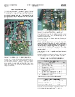
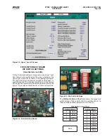
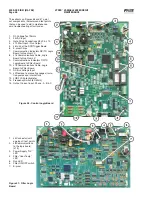
What is the test button on the Vyper
™
logic board?
When the Vyper
™
is not running, this button may be used
to test operation of the logic outputs to the Vyper
™
power
module, as well as the operation of the gate driver board on
the IGBT module. When the button is depressed, six output
LEDs on the Logic Board alternately light the three plus (+)
LEDs then the three (-) LEDs. At the same time, six LEDs on
the gate driver board will alternate between dim and bright
intensity. Several conditions can inhibit this test function:
• If any
VSD fault exists.
• If the unit is in precharge.
• If the SCR trigger is enabled.
• If the VSD unit is running.
• A 4-minute timer is part of this function to ensure that the
DC Link Voltage is discharged to a safe level. This timer
must time out before the Test Button will function.
ADDENDUM
The following materials provide additional information for
operation and functioning of the Frick Vyper
™
variable speed
drive. Strongly recommended is the Frick Quantum
™
LX Com-
pressor Control Panel Operations Manual, which explains all
the Vyper
™
screens that are not covered in this manual.
In addition to this manual it is strongly recommended that
you have the Installation Operation and Maintenance manual
to the specifi c refrigeration system which will be controlled
by the Frick Vyper
™
.
VYPER
™
ALARMS / SHUTDOWNS
In addition to the Alarms and Shutdowns that the Quantum
™
LX
software generates for the basic compressor package, the
Vyper
™
unit has a separate set of Alarms and Shutdowns
which may be generated, and displayed at the Quantum
™
LX
control panel screen. Unlike the Quantum
™
LX alarms and
shutdowns, which are displayed in a text format, the alarms
and shutdowns that the Vyper
™
generates are numerical in
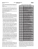
nature. To view the numerical alarm or shutdown, compare the
number that is shown with the table that appears later in this
section for the text message. When a Shutdown occurs, the
display backlight will fl ash on and off to alert an operator of the
shutdown. This visual alarm will help get the attention of the
operator in a noisy engine room environment where audible
alarms may not be heard. Pressing any key on the keypad will
clear the fl ashing backlight alarm. The FRICK VYPER
™
FAULT
CODES table shows the full listing of fault codes. A detailed
description and troubleshooting recommendations follow.
There are two types of Quantum
™
control panels: the stan-
dard Quantum
™
and the Quantum
™
LX. The alarms and
messages differ between the two models. The messages of
the Quantum
™
LX are listed in this manual.
FAULT CODE DESCRIPTIONS
Fault 1 : VSD Interface Board Power Supply
Message
Quantum: “Fault 1”
Quantum LX: “VSD Interface Board Power Supply Fault”
This fault is set on every power-up. It is immediately cleared,
and logged in the fault history to record the occurrence of
the power loss.
Fault 2 : Interface Board Loss of Motor Current
Message
Quantum: “Fault 2”
Quantum LX: “VSD Interface Board Loss of Motor Current”
This fault occurs whenever the Vyper
™
is running and a motor
current of less than 10 % FLA is detected for at least twenty-
fi ve continuous seconds. To clarify, this fault is only checked
when the Run Acknowledge output is engaged. Therefore, it
is NOT checked during STANDBY, which prevents this fault
from occurring during STANDBY.
Fault 3: VSD Interface Board Motor Current > 15%
Message
Quantum: “Fault 3”
Quantum LX: “VSD Interface Board Motor Current > 15%”
This fault occurs whenever the Vyper
™
is not running and a
motor current of greater than 15 % FLA is detected for at
least ten seconds.
Fault 4: VSD Interface Board Run Signal
Message
Quantum: “Fault 4”
Quantum LX: “VSD Interface Board Run Signal Fault”
This fault occurs if the Run Signal from the Quantum Control
Panel is high, but the speed command being sent over the
RS-485 communications link is zero. It may also occur if the
Run Signal is low, but the speed command is not zero. Both
conditions must be present for fi ve seconds before the fault
is set, and are only applicable in automatic mode.
Содержание Frick vyper VYA PG -46
Страница 15: ...VYPER VARIABLE SPEED DRIVE INSTALLATION S100 200 IOM MAY 08 Page 15 Liquid Cooled Vyper P I Diagram Economized ...
Страница 24: ...VYPER VARIABLE SPEED DRIVE INSTALLATION S100 200 IOM MAY 08 Page 24 ANALOG BOARD WIRING Figure 21 ...
Страница 62: ...S100 200 IOM MAY 08 Page 62 VYPER VARIABLE SPEED DRIVE NOTES ...
Страница 63: ...S100 200 IOM MAY 08 Page 63 VYPER VARIABLE SPEED DRIVE NOTES ...

