VYPER
™
VARIABLE SPEED DRIVE
MAINTENANCE
S100-200 IOM (MAY 08)
Page 52
Same comments as Fault 17 except applying to Phase B
Instantaneous Current
Fault 19: High Phase C Instantaneous Current
Message
Quantum: “Fault 19”
Quantum LX: “VSD High Phase C Instantaneous Current”
Same comments as Fault 17 except applying to Phase C
Instantaneous Current
Fault 21: Vyper Phase A Gate Driver
Message
Quantum: “Fault 21”
Quantum LX: “VSD Phase A Gate Driver Fault”
The unit’s phase bank assembly shall contain one IGBT
gate driver control board. This board monitors the satura-
tion voltage drop across each IGBT while gated on. If the
IGBT’s saturation voltage exceeds the prescribed limit, the
gate driver will make the determination that a short circuit
is present. This in turn shall cause the unit to trip and the
Quantum
™
LX Panel shall display the message Fault 21. If the
driver board’s power supply voltage falls below the permis-
sible limit, this same message shall be generated.
A second level of overcurrent protection exists on the Vyper
™
gate driver board. The collector-to-emitter voltage of each
IGBT is checked continuously while the device is being
turned on. This is also called the collector-to-emitter satura-
tion voltage. If the voltage across the IGBT is greater than a
set threshold, the IGBT is turned off and a shutdown pulse
is sent to the Vyper
™
logic board shutting down the entire
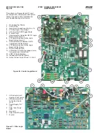
system. To diagnose the problem, fi rst check the LED’s on
the gate driver board of the Vyper
™
power unit. Usually one
of the six LED’s will be out. This clearly points to a bad gate
driver, and requires replacement of the Vyper
™
power module.
If all LED’s are lit, and the problem repeatedly occurs in one
phase, swap all three pole cables at the logic board J8, J9,
and J10. Plug J8 into J9, J9 into J10, and J10 into J8. If the
display now reports a trip in a different phase, the problem
is either in the Vyper
™
power module or gate driver board, or
in the cable that feeds the gate driver board from the Vyper
™
Logic board. The fault could also be cause by a problem in
the drive line. Ensure that the compressor is free to rotate.
If the display continues to report a gate driver FLT in the
same phase, even with cables swapped, the problem is in the
Vyper
™
Logic board. Once you have fi nished troubleshooting,
be sure to put all of the cables back into their original mating
connectors. Also, be aware that a gate driver fault can be
initiated when the Vyper
™
is not running if a power supply
has failed on the gate driver board.
Check that the LRA rating of the motor is not higher than the
LRA rating of the drive.
Fault 22: Vyper Phase B Gate Driver
Message
Quantum: “Fault 22”
Quantum LX: “VSD Phase B Gate Driver Fault”
Same comments as Fault 21 except applying to Phase B
Gate Driver.
Fault 23: Vyper Phase C Gate Driver
Message
Quantum: “Fault 23”
Quantum LX: “VSD Phase C Gate Driver Fault”
Same comments as Fault 21 except applying to Phase C
Gate Driver.
Fault 24: Vyper Single Phase Input Power
Message
Quantum: “Fault 24”
Quantum LX: “VSD Single Phase Input Power Fault”
The Vyper’s SCR Trigger Control board contains circuitry that
checks the three-phase mains for the presence of all three
line voltages. If all line voltages are not present, the unit will
trip and the Quantum
™
LX Panel will display the message
Fault 24.
This shutdown is generated by the SCR Trigger board and
relayed to the Vyper
™
Logic board to initiate a system shut-
down. The single-phase control uses circuitry to detect the
loss of any one of the three input phases. The trigger board
will detect the loss of a phase within one half line cycle of the
phase loss. An LED on the SCR Trigger board will indicate
that the board is detecting the fault, and not a wiring problem
between the trigger board and the Vyper
™
logic board. This
message is also displayed every time power to the Vyper
™
is
restored or if the input power dips to a very low level. Usually
it indicates that someone has opened the disconnect switch.
Many times one of the input fuses (F1-F3) to the trigger
board has failed.
Fault 27: Vyper 105% Motor Current Overload
Message
Quantum: “Fault 27”
Quantum LX: “VSD 105% Motor Current Overload Fault”
The Vyper
™
Logic Board generates this shutdown by read-
ing the current from the 3 output current transformers. The
shutdown is generated when the Vyper
™
Logic board has
detected that the highest of the three output phase currents
has exceeded 105% of the programmed 100% full load amps
( FLA) value for more than 40 seconds. If this is detected,
the unit will trip and the Quantum
™
LX panel will display the
fault message. The 100% FLA setpoint is determined by
adjustment of the FLA trim pot on the logic board. This fault
will require clearing using the manual reset button located
on the Logic board. The overload timer resides in the Field
Programmable Gate Array which is programmed by the serial
E^^2 PROM on unit power-up.
Fault 28: Vyper High DC Current Bus Voltage
Message
Quantum: “Fault 28”
Quantum LX: “Vyper High DC Current Bus Voltage”
The DC link overvoltage trip level is determined by hardware
on the logic board and it is designed to trip the unit at 745
+/- 17 VDC for both 60 and 50 Hz VSD’s. If the DC bus cur-
rent exceeds this level, the unit will trip and the Quantum
™
LX
Panel will display the message Fault 28.
If this shutdown occurs, it will be necessary to look at the level
of the 460 VAC applied to the Vyper
™
. The specifi ed voltage
range is 414 to 508. If the incoming voltage is in excess of
508, steps should be taken to reduce the voltage to within
the specifi ed limits.
Fault 29: Vyper Logic Board Power Supply
Message
Quantum: “Fault 29”
Quantum LX: “VSD Logic Board Power Supply Fault”
Содержание Frick vyper VYA PG -46
Страница 15: ...VYPER VARIABLE SPEED DRIVE INSTALLATION S100 200 IOM MAY 08 Page 15 Liquid Cooled Vyper P I Diagram Economized ...
Страница 24: ...VYPER VARIABLE SPEED DRIVE INSTALLATION S100 200 IOM MAY 08 Page 24 ANALOG BOARD WIRING Figure 21 ...
Страница 62: ...S100 200 IOM MAY 08 Page 62 VYPER VARIABLE SPEED DRIVE NOTES ...
Страница 63: ...S100 200 IOM MAY 08 Page 63 VYPER VARIABLE SPEED DRIVE NOTES ...


