VYPER
™
VARIABLE SPEED DRIVE
INSTALLATION - OPERATION - MAINTENANCE
S100-200 IOM (MAY 08)
Page 3
PREFACE
This manual has been prepared to acquaint the owner and
service person with the
INSTALLATION, OPERATION, and
MAINTENANCE
procedures as recommended by Johnson
Controls-Frick for the Frick Vyper
™
Variable Speed Drive
unit.
For information about the functions of the Quantum
™
LX
Control panel, communications, specifi cations, and wiring
diagrams, please see the applicable and most current Frick
documentation.
It is most important that these units be properly applied to an
adequately controlled refrigeration system. Your author ized
Frick repre sentative should be consulted for expert guidance
in this determination.
Proper performance and continued satisfaction with these
units is dependent upon:
CORRECT INSTALLATION
PROPER OPERATION
REGULAR, SYSTEMATIC MAIN TENANCE
To ensure correct installation and application, the equipment
must be properly selected and connected to a properly de-
signed and installed system. The Engineering plans, piping
layouts, etc. must be detailed in accordance with the best
practices and local codes, such as those outlined in ASHRAE
literature.
The Frick Vyper
™
is a sophisticated piece of electronic con-
trol equipment. All safety precautions consistent with opera-
tion of high current and voltage electrical equipment should
be strictly enforced.
JOB INSPECTION
Immediately upon arrival examine all crates, boxes, and
exposed compressor and component surfaces for damage.
Unpack all items and check against shipping lists for any
possible shortage. Examine all items for damage in transit.
TRANSIT DAMAGE CLAIMS
All claims must be made by consignee. This is an ICC re-
quirement. Request immediate inspec tion by the agent of the
carrier and be sure the proper claim forms are executed.
Contact Johnson Controls-Frick, Sales Administration
Depart ment, in Waynesboro, PA to report dam age or short-
age claims.
NOTE: Damage must be photographically
documented.
UNIT IDENTIFICATION
Each Vyper
™
has a unit identifi cation label located on the
right side of the cabinet. The data plate contains the John-
son Controls-Frick Part Number, the unique Serial Number,
and the basic Model Number for the unit. In addition, the
data label also has electrical information pertinent to the
individual unit.
NOTE: When inquiring about the Vyper
™
or ordering
spare parts, please provide the MODEL Number and
SERIAL Number from the data plate.
Figure 1 - Vyper
™
Data Plate
Always wait 5 minutes after Vyper
™
power is off to open the cabinet.
This time allows the capacitors to
discharge. Failure to do so could result in serious in-
jury or death.
Содержание Frick vyper VYA PG -46
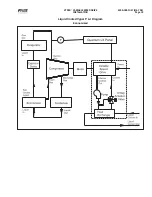
Страница 15: ...VYPER VARIABLE SPEED DRIVE INSTALLATION S100 200 IOM MAY 08 Page 15 Liquid Cooled Vyper P I Diagram Economized ...
Страница 24: ...VYPER VARIABLE SPEED DRIVE INSTALLATION S100 200 IOM MAY 08 Page 24 ANALOG BOARD WIRING Figure 21 ...
Страница 62: ...S100 200 IOM MAY 08 Page 62 VYPER VARIABLE SPEED DRIVE NOTES ...
Страница 63: ...S100 200 IOM MAY 08 Page 63 VYPER VARIABLE SPEED DRIVE NOTES ...


