DINAMAP*
Compact
Vital Signs Monitor
41
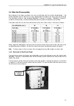
3.4 Monitor Disassembly
Most alignment and repair operations can only be performed with the monitor disassembled. This
section describes how to remove the covers, disassemble the chassis and remove the circuit boards.
The description refers to fully equipped DINAMAP*
Compact
TS models. DINAMAP*
Compact
T
models do not have SpO
2
functions and therefore the SpO
2
related components are not fitted.
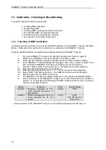
The build revision of your unit can be determined by the serial number break. These are as follows:-
Overall Build Revision
02
04
06
Serial Nos.
Boards
##000
3000
aa
TO
##000
4999
aa
##000
5000
aa
TO
##000
9999
aa
##00
10000
aa
TO
date
8600EB
Rev 01
Rev 01
Rev 01
8610AB & circuit diagram
Rev 01
Rev 03
N/A
8620AB & circuit diagram
Rev 02
Rev 04
Rev 06
8630AB & circuit diagram
Rev 01
Rev 03
Rev 04
8640AB & circuit diagram
Rev 02
Rev 04
Rev 04
8650AB & circuit diagram
Rev 02
Rev 04
Rev 05
8760AB & circuit diagram
N/A
N/A
Rev 01
Before beginning disassembly, disconnect the line power cord from the power socket and remove the
rechargeable lead-acid battery. Be careful to observe anti-static handling precautions throughout.
Note
: Pictures shown are from a revision 06 unit, appearance may differ slightly on earlier units.
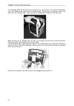
3.4.1 Removal of the Front Panel
The front panel contains the Display board (8630AB), Liquid Crystal Display module and Switch board
(8640AB). The Rotor, Temperature probe socket and SpO
2
socket (model TS) are also mounted on the
inside of the panel.
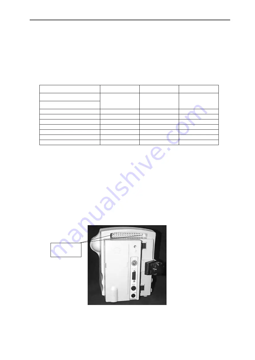
The front panel must be removed if access to any of the boards or modules mounted on it or behind it
is required. To remove the panel, release the two Pozidriv
TM
screws mounted inside the hand recess of
the instrument’s rear enclosure.
Front panel
retaining
screws

