


Page 7 of 28
Technical Support
1 866 228-3762
Systems Engineer
321-243-0600
For Layer 3 IPv4 testing, configure the following additional settings:
Folder
Option
Value(s)
Comment
IP
Source IP Type
Static
Options displayed after tapping
Source IP Address field.
Source IP
See Work Order
Default Gateway
See Work Order
Subnet Mask
See Work Order
Destination IP
See Work Order
Options displayed after tapping
Destination IP Address field.
11.
View Results
Press the
RESULTS
button, to display the Results screen.
12.
Turn Laser On
If testing an Optical link, select the Laser tab in the lower part of the
screen and press
Laser Off
. The button will turn Yellow and be
relabeled to indicate the
Laser
is
On
.
13.
Check LEDs
Press the
Restart
soft key on the Right side of the display to reset test
results. A
Green
Signal Present LED indicates that the T-BERD is
receiving an optical signal from the near end Ethernet Switch.
Green
Sync Acquired
and
Link Active
LEDs indicate that the T-BERD has
successfully connected to the near end Ethernet switch and the Ethernet
link is active.
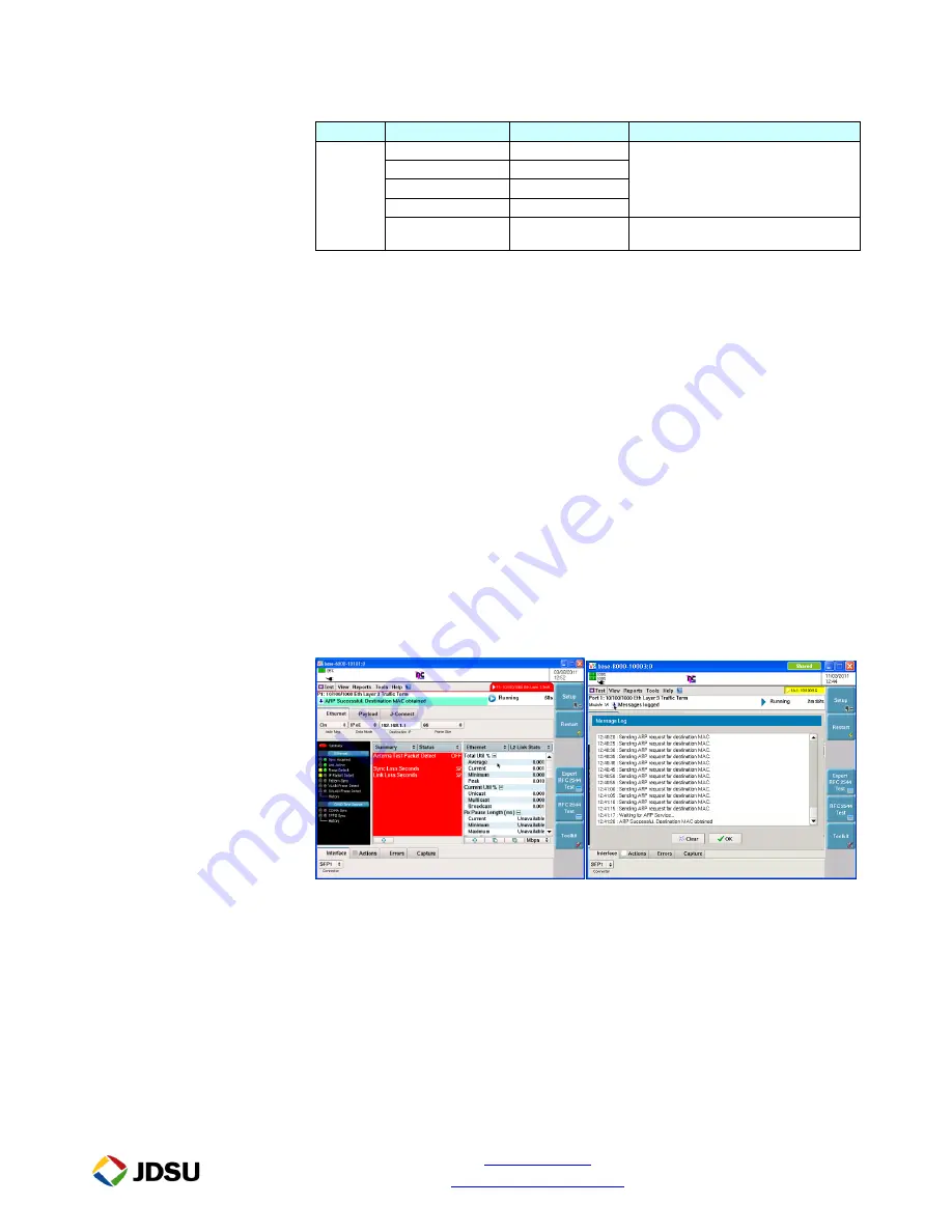
14.
Check ARP Status
If you are running a
Layer 3 IPv4 Test
, verify that the final message in
the Message bar is “ARP Successful. Destination MAC obtained.” If
the message bar displays: “Messages logged,” tap the down arrow next
to “Messages logged” and verify that the final message is “ARP
Successful. Destination MAC obtained.” Click OK to exit the log.
If “
ARP Successful”
is not displayed, verify that the T-BERD’s IP menu
is configured correctly, as outlined above.
15.
Start RFC
Press the
Enhanced RFC 2544
soft key on the Right side of the
Results
screen.
16.
Select Config
Select the
Configs
tab. If this is the first time using the RFC2544 test,
tap
[New]
, enter a name for the new configuration, then tap
[OK]
.
Otherwise, choose the saved Test Configuration.


