


Getting Started –
33
After the module is physically in place, connect one transmitter, normally the C-band, to the port
marked “TX1”. The connector must be FC/APC. Connect the other transmitter to the port
marked “TX2” using the FC/APC end of the fiber from the second transmitter. Finally, use the
supplied FC/APC-FC/APC jumper to connect the output of the DBSSM to the input to the Control
Module.
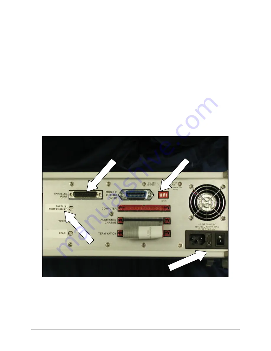
Connecting the Parallel Port Interface
To connect the parallel port interface (PPI) to the receiver make sure that the computer you are
about to use has its parallel port configured to SPP or bi-directional protocol. Please contact your
system support specialist to verify the settings if needed.
1. Connect the supplied 25-pin cable to the printer port on the computer.
2. Connect the other end of the cable to the connector labeled Parallel Interface on the back of
the receiver.
3. Press down the upper part of the right-most DIP switch, labeled Parallel Port Enable on the
back of the receiver. Power up the OWB. The Parallel Interface LED should come on.
Figure 9. DIP switch settings.
4. If you already have SWS software installed on the computer, please start Configure SWS I/O
Interface program. A shortcut is located under the Start button, in the Programs, SWS15100
section. Choose the parallel port interface option and also select the LPT port, to which you
DIP Switches
OWB Power Switch
Parallel Interface LED
Parallel Port Interface
Artisan Technology Group - Quality Instrumentation ... Guaranteed | (888) 88-SOURCE | www.artisantg.com
Содержание SWS15100
Страница 3: ...Artisan Technology Group Quality Instrumentation Guaranteed 888 88 SOURCE www artisantg com...
Страница 13: ...Artisan Technology Group Quality Instrumentation Guaranteed 888 88 SOURCE www artisantg com...
Страница 201: ...186 Programming Guide Artisan Technology Group Quality Instrumentation Guaranteed 888 88 SOURCE www artisantg com...


