


Chapter 5
Configuring the Meter
Configure – General Tab
52
DSAM Help User Guide
Rev. 001
7
If the keypad fails to function properly, contact your
JDS
Uniphase Corporation Customer Service Representative
.
8
Press the
Done
softkey.
Using Virtual DSAM
To use Virtual DSAM
1
Connect an
Ethernet cable
to the DSAM.
2
Press
Configure
.
3
Press the
General
softkey.
4
Using the arrow keys, select
Diagnostic
.
5
Press
ENTER
.
6
Using the arrow keys, select
Use Virtual DSAM
.
7
Press the
Select
softkey.
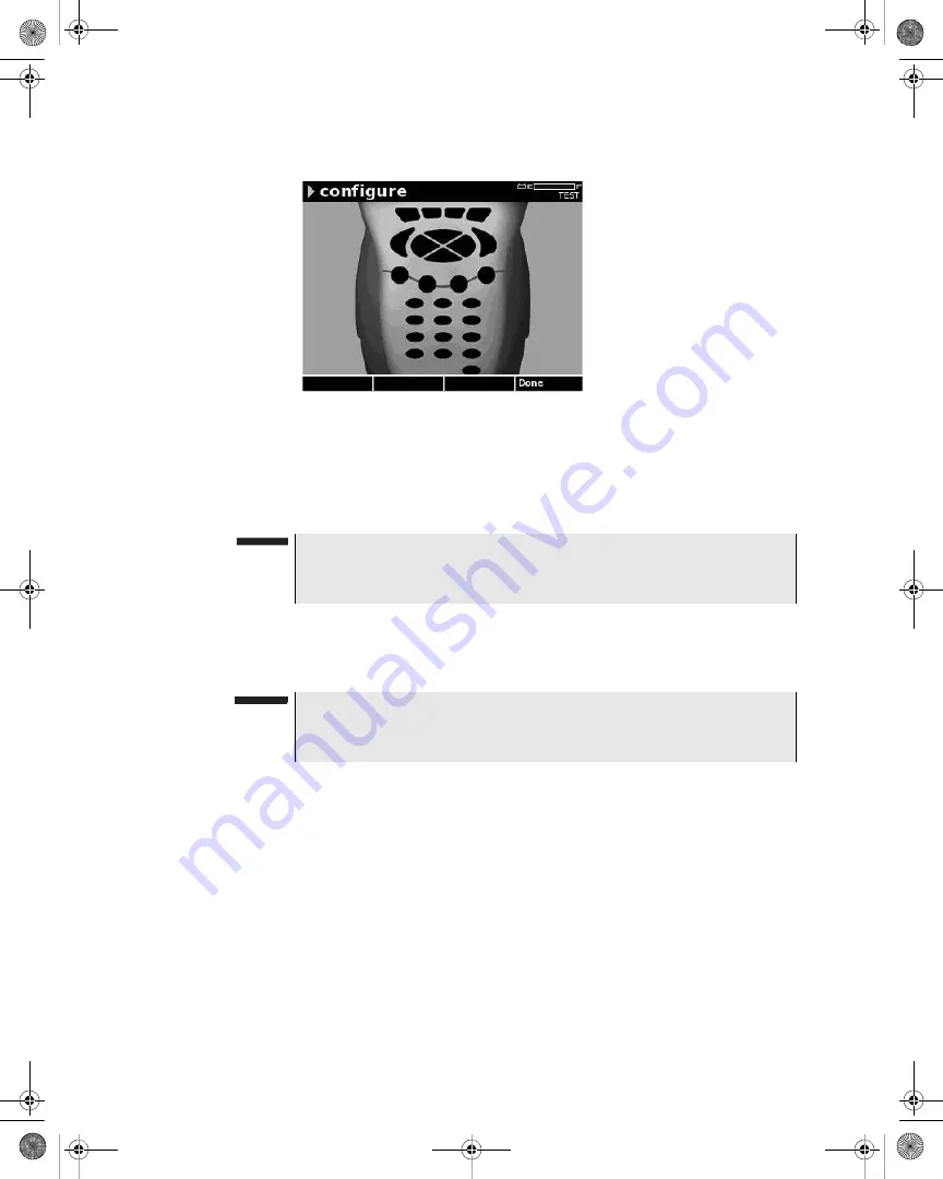
Figure 41
Configure – Keypad Test
NOTE
During the test, the only keys that function normally are the Power
key and the Done softkey.
NOTE
In order to use Virtual DSAM, your computer and the Ethernet cable
must be connected to the same IP network or a public IP network.
21128026 R001 DSAM Help User Guide.book Page 52 Thursday, February 5, 2009 2:02 PM


