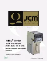
manualshive.com logo in svg
background image

ID =Pix+R.jpg

© 2007, JCM American, Corporation

Office:

 (800) 683-7248

Technical Support:

 (702) 651-3444

FAX:

 (702) 651-0214


E-Mail: 

[email protected]

Web-Site: 

www.jcm-american.com

WBA

®

 Series

World Bill Acceptor 


(WBA-1x/2x -SS & SS2) 

Operation and Maintenance Manual 
(Revision 1)

JCM Part No. 960-000076R_Rev. 1

Содержание WBA Series

Страница 1: ...fice 800 683 7248 Technical Support 702 651 3444 FAX 702 651 0214 E Mail techsupport jcm american com Web Site www jcm american com WBA Series World Bill Acceptor WBA 1x 2x SS SS2 Operation and Mainte...

Страница 2: ...rk of JCM American Corporation All other product names mentioned herein may be registered trademarks or trademarks of their respective companies Furthermore and are not always mentioned in each case t...

Страница 3: ...P Switch Configurations 2 6 WBA 1X and WBA 2X Head Sensor Lens Differences 2 6 Retrieving Bills 2 7 Clearing a Bill Jam 2 7 Cleaning Preventive Maintenance 2 8 Available Cleaning Card 2 8 Card Feature...

Страница 4: ...TING 6 1 Workbench Tool Requirements 6 1 Software Download Preparation 6 1 Software Downloading Procedure 6 2 Program Installation 6 2 Calibration Procedure 6 2 Calibration Error Messages 6 6 Sensor S...

Страница 5: ...st PH07 A 7 Transport Sensor Test A 7 Transport Sensor Locations A 8 Sensor Circuit Board and Motor Locations A 8 Bill Acceptance Test A 9 Bill Acceptance Test Modes A 9 Bill Identification in Bill Ac...

Страница 6: ...JCM Part No 960 000076R_Rev 1 2007 JCM American Corporation i v WBA 1x 2x SS SS2 Series Table of Contents THIS PAGE INTENTIONALLY LEFT BLANK...

Страница 7: ...fferences 2 6 Figure 2 10 Removing the WBA Cash Box 2 7 Figure 2 11 Retrieving Bills 2 7 Figure 2 12 Clearing an Entrance Bill Jam 2 7 Figure 2 13 Clearing a Transport Unit Bill Jam 2 7 Figure 2 14 Cl...

Страница 8: ...sembly 4 8 Figure 4 31 Lower Timing Belt Access 4 8 Figure 4 32 Lower Timing Belt Removal 4 9 Figure 4 33 Pusher Mechanism Removal 4 9 Figure 4 34 Pusher Mechanism Cover Removal 4 9 Figure 4 35 Coupli...

Страница 9: ...eens 6 5 Figure 6 23 Writing Adjustment Data Screen 6 5 Figure 6 24 End Calibration Screen 6 5 Figure 6 25 Typical Error Message Screen 6 6 Figure 7 1 Entire WBA Unit Exploded View 7 1 Figure 7 2 WBA...

Страница 10: ...JCM Part No 960 000076R_Rev 1 2007 JCM American Corporation viii WBA 1x 2x SS SS2 Series List of Figures THIS PAGE INTENTIONALLY LEFT BLANK...

Страница 11: ...2 WBA 2X SS Validator Sensor Names 6 6 Table 7 1 Entire WBA Unit Parts List 7 2 Table 7 2 WBA 12 13 22 23 24 25 Acceptor Head Collective Parts List 7 5 Table 7 3 WBA Transport Unit Collective Parts L...

Страница 12: ...JCM Part No 960 000076R_Rev 1 2007 JCM American Corporation x WBA 1x 2x SS SS2 Series List of Tables THIS PAGE INTENTIONALLY LEFT BLANK...

Страница 13: ...e Unit Dimensions Unit Dimensions with WBA Faceplate Unit Dimensions with ICB Standard Cash Box Dimensions Country Codes In order to make operation of this device easier and make navigation within thi...

Страница 14: ...lean dust and debris from the bill path Table 1 1 Model Number Specifications No Model WBA SS No 1 2 3 4 5 6 7 8 9 1 Acceptor head type 1 1x Head magnetic sensors enhanced 2 2x Head optical sensors en...

Страница 15: ...ard is now available Refer to Cleaning Preventive Maintenance on page 8 of Section 2 of this manual for further information concerning its avail ability and use 7 Inserting worn or damaged bills may a...

Страница 16: ...65mm up to 6 7 in 170mm with a Steel Cash Box Insertion Direction Refer to Software Specifications relative to bills being used Processing Speed Approximately 2 seconds from bill insertion to vend sig...

Страница 17: ...wide The length of bills read are from 125mm t 170mm See Figure 1 5 DIP Switch Programmable Bill Acceptance DIP switch settings to accept reject bills Up to 7 denominations acceptable Accept or Reject...

Страница 18: ...1 6 Section 1 World Bill Acceptor WBA 1x 2x SS SS2 General Information Standard Unit Dimensions Figure 1 7 illustrates the WBA 1x SS standard unit dimensions NOTE All Units are in Millimeters Figure 1...

Страница 19: ...gland GBR Great Britain England GBR B Great Britain Gibraltar GBR GBI Great Britain Isle Of Man GBR MAN Greece GRC Greece GRC B Guatemala MGT Honduras HND Hong Kong HKG Hungary HUN Iceland ISL India I...

Страница 20: ...ngapore SGP Singapore SGP B Slovakia SVK Slovenia SVN South Africa ZAF Spain ESP Sri Lanka LKA Sweden SWE Switzerland CHE Switzerland CHE3 Switzerland CHE B Taiwan Republic Of China TWN Tanzania TZA T...

Страница 21: ...Unless your WBA had been used with previous software installed the correct bill guides should be installed in the acceptor unit Each software package has designated bill guide types assigned to it i e...

Страница 22: ...from the front until you hear a click See Figure 2 4 Be sure to push the guides into the assembly in the correct direction Input Output Circuits 1 Figure 2 5 and Figure 2 6 illustrate the various WBA...

Страница 23: ...l Name Function 1 LED LED drive anode 2 LED LED drive cathode 3 NC Reserved No Connection 4 NC Reserved No Connection Header 53103 0530 Japan Molex Contact Type 50083 8 14 Japan Molex Housing 51030 05...

Страница 24: ...ive serial data signal input line into WBA 7 GND I F Zero 0 Volt DC Interface power 8 NC Reserved No Connection 9 NC Reserved No Connection 10 NC Reserved No Connection 11 NC Reserved No Connection 12...

Страница 25: ...Interconnection Figure 2 7 Typical WBA 1X 2X SS Cabling Requirements Figure 2 7 illustrates the typical cabling requirements between the Host Machine and a WBA 1X 2X SS Bill Validator Figure 2 8 Typic...

Страница 26: ...ill enabled 8 TEST Mode NORMAL Mode TITO Ticket In Ticket Out Table 2 6 DIP Switch Settings Continued WBA Right Side Panel Switches Default Setting ALL Switches are OFF Switch No Switch ON Switch OFF...

Страница 27: ...he Acceptor as indicated by the small arrows in Figure 2 12 and 2 Open the units Acceptor s Cover See Figure 2 12 a 3 Remove the jammed bill See Figure 2 12 b 4 If the jammed bill cannot be removed by...

Страница 28: ...ce between regular Preventive Maintenance intervals This is the only cleaning card authorized for use on the WBA Gaming Validator See Figure 2 16 CARD FEATURES A unique Waffletechnology design that hu...

Страница 29: ...ion 2 9 Installation Operation World Bill Acceptor WBA 1x 2x SS SS2 Section2 ID 003 Standard Interface Operational Flowchart Figure 2 17 depicts a typical ID 003 Interface WBA bill acceptance flow pro...

Страница 30: ...JCM Part No 960 000076R_Rev 1 2007 JCM American Corporation 2 1 0 Section 2 World Bill Acceptor WBA 1x 2x SS SS2 Installation Operation THIS PAGE INTENTIONALLY LEFT BLANK...

Страница 31: ...es World Bill Acceptor WBA 1x 2x SS SS2 Section 3 3 COMMUNICATIONS This section was intentionally left out due to a Non Disclosure Agreement requirement If this information is required please contact...

Страница 32: ...JCM Part No 960 000076R_Rev 1 2007 JCM American Corporation 3 2 World Bill Acceptor WBA 1x 2x SS SS2 THIS PAGE INTENTIONALLY LEFT BLANK...

Страница 33: ...f Jewelers Phillips Screw Drivers E Clip E Ring Plyers Needle Nose Plyers Tweezers Primary Unit Disassembly The following instructions are provided to perform an initial disassembly of the World Bill...

Страница 34: ...Lower Sensor Circuit Board Removal Perform the following steps to remove the WBA Lower Sensor Printed Circuit Board 1 Remove the four 4 Lower Sensor Board Cover mounting screws See Figure 4 6 a locate...

Страница 35: ...pop out of their slots Remove the two pins from the shaft See Figure 4 9 b 5 Pull the shaft completely out of the housing and remove the two 2 Belt Tension Assemblies See Figure 4 9 c 6 Remove the E r...

Страница 36: ...4 14 a and remove the single 1 screw securing the Val idator Catch Bar to remove its beam See Figure 4 14 b 6 Pull the CPU Circuit Board out of the Trans port Assembly as indicated by the large arrow...

Страница 37: ...4 18 b and 4 Disconnect the harness plug from the Encoder Sensor Board to remove it from the assembly See Figure 4 18 c Transport Drive Motor Removal Perform the following steps to remove the WBA Tra...

Страница 38: ...mounting screws and disconnect the harness plug from the board to remove it from the assembly See Figure 4 22 a b Solenoid Lever Assembly Removal Perform the following steps to remove the WBA Transpo...

Страница 39: ...sembly 1 Remove the single 1 screw retaining the Feed Out Sensor and Lens to the assembly See Figure 4 26 a b Upper Timing Belt Removal Perform the following steps to begin removal of the WBA Transpor...

Страница 40: ...c The shaft can now be removed from the left side of the assembly See Figure 4 29 d 5 Remove the loose Timing Belts Figure 4 8 better illustrates a complete Transport Timing Belt Shaft component disa...

Страница 41: ...erform the following steps to remove the WBA Cash Box Pusher Mechanism Cover 1 Remove the six 6 Pusher Mechanism Cover mounting screws located on each side of the pusher mechanism assembly See Figure...

Страница 42: ...See Figure 4 36 c 5 Remove the Shaft Tension Spring set on the small drive gears shaft end see f inset on the shaft See Figure 4 36 d 6 Separate the Cash Box side and remove the two 2 Timing Belts See...

Страница 43: ...provides the World Bill Acceptor WBA Series wiring diagrams and component parts lists for the following items WBA Primary Components WBA 14 SS3B System Wiring Diagram WBA 15 SS3B System Wiring Diagram...

Страница 44: ...JCM Part No 960 000076R_Rev 1 2007 JCM American Corporation 5 2 Section 5 World Bill Acceptor WBA 1x 2x SS SS2 Wiring Diagrams THIS PAGE INTENTIONALLY LEFT BLANK...

Страница 45: ...No 960 000076R_Rev 1 2007 JCM American Corporation 5 3 Wiring Diagrams World Bill Acceptor WBA 1x 2x SS SS2 Section5 WBA 14 SS3B System Wiring Diagram Figure 5 2 WBA 14 SS3B Bill Acceptor System Wirin...

Страница 46: ...o 960 000076R_Rev 1 2007 JCM American Corporation 5 4 Section 5 World Bill Acceptor WBA 1x 2x SS SS2 Wiring Diagrams WBA 15 SS3B System Wiring Diagram Figure 5 3 WBA 15 SS3B Bill Acceptor System Wirin...

Страница 47: ...No 960 000076R_Rev 1 2007 JCM American Corporation 5 5 Wiring Diagrams World Bill Acceptor WBA 1x 2x SS SS2 Section5 WBA 24 SS3B System Wiring Diagram Figure 5 4 WBA 24 SS3B Bill Acceptor System Wirin...

Страница 48: ...o 960 000076R_Rev 1 2007 JCM American Corporation 5 6 Section 5 World Bill Acceptor WBA 1x 2x SS SS2 Wiring Diagrams WBA 25 SS3B System Wiring Diagram Figure 5 1 WBA 25 SS3B Bill Acceptor System Wirin...

Страница 49: ...xternal Power Supply Part No 550 100042 or equivalent PC containing a free COM Port OS Windows 2000 XP The latest WBA Download Program CD obtain from your JCM Sales Representative Black White and Mag...

Страница 50: ...gram i e ADJ10Win_e exe for WBA 12 13 ADJ20Win_e exe for WBA 22 23 24 25 Calibration Procedure When the WBA 1x Series Adjustment Program begins the Figure 6 3 Screen will appear Before proceeding chec...

Страница 51: ...e Acceptor Head and make sure that the tabs on both side of the Acceptor Head firmly lock in place See Figure 6 11 b 9 Click on the OK Screen Button to start the Black Reference Paper calibration proc...

Страница 52: ...ll appear 13 When the paperless calibration process is complete the Figure 6 17 Screen will appear 14 Insert the MAG Head Test Board into the Acceptor and find the location where the second line of MA...

Страница 53: ...rm 1 Screen will appear providing a prompt asking if the current adjustment data results should be written into the Acceptor Head Memory 20 Press the Save new adjustment Screen Button and then the Cli...

Страница 54: ...Validator as instructed by the monitor When calibration error occurs the sensor signal name and the signal value involved in the error will be displayed on the line below the The gain of the following...

Страница 55: ...ction provides product exploded views and parts lists for the World Bill Acceptor Series WBA This section contains the following information Entire WBA Unit View and Parts List Acceptor Unit View and...

Страница 56: ...24 25 2 119952 It is a interim EDP Please contact JCM headquarters before you order WBA 12 22 SS Transfer Unit WBA 12 22 SS 119964 WBA 13 23 SS Transfer Unit WBA 13 23 SS 102433 WBA 24 SS2 Transfer U...

Страница 57: ...0 000076R_Rev 1 2007 JCM American Corporation 7 3 Exploded Views and Parts Lists World Bill Acceptor WBA 1x 2x SS SS2 Section7 WBA 12 13 Acceptor Head Exploded Views Figure 7 2 WBA 12 13 Acceptor Head...

Страница 58: ...76R_Rev 1 2007 JCM American Corporation 7 4 Section 7 World Bill Acceptor WBA 1x 2x SS SS2 Exploded Views and Parts Lists WBA 22 23 24 25 Acceptor Head Exploded View Figure 7 3 WBA 22 23 24 25 Accepto...

Страница 59: ...0943RE0124J Guide A MG R WBA 12 13 054623 0943RE0101H Guide A FOT R WBA 22 23 24 25 113 052466 0943PT0102C V Top Cover R 114 053623 0943PT0109C Earth Plate Spring L 115 053624 0943PT0108C Earth Plate...

Страница 60: ...22 23 24 25 140 052587 0943SH0101A OL Roller Shaft 141 081620 O Ring P11 EPDM70 142 052509 0943RE0108A OL Roller R 143 052638 0943CS0102 VL Spring 144 052511 0943RE0110A SP Collar A R 145 052510 0943...

Страница 61: ...0076R_Rev 1 2007 JCM American Corporation 7 7 Exploded Views and Parts Lists World Bill Acceptor WBA 1x 2x SS SS2 Section7 WBA Transport Unit Exploded Views Continued Figure 7 4 WBA Transport Unit Exp...

Страница 62: ...0076R_Rev 1 2007 JCM American Corporation 7 8 Section 7 World Bill Acceptor WBA 1x 2x SS SS2 Exploded Views and Parts Lists WBA Transport Unit Exploded Views Continued Figure 7 5 WBA Transport Unit Ex...

Страница 63: ...0076R_Rev 1 2007 JCM American Corporation 7 9 Exploded Views and Parts Lists World Bill Acceptor WBA 1x 2x SS SS2 Section7 WBA Transport Unit Exploded Views Continued Figure 7 6 WBA Transport Unit Exp...

Страница 64: ...JCM Part No 960 000076R_Rev 1 2007 JCM American Corporation 7 1 0 World Bill Acceptor WBA 1x 2x SS SS2 THIS PAGE INTENTIONALLY LEFT BLANK...

Страница 65: ...ST TR 2 Gear 1 R WBA SS 212 070735 0664RE0202A ST TR Gear 182 R WBA SS2 052536 0943RE0211B ST Gear 1 R 213 052615 0943ST0204G ST Gear Stud 1 214 052539 0943RE0214A ST TR Gear 2 R 215 052508 0943RE010...

Страница 66: ...0201B Catch Shaft 243 116356 943 843 06 01A 01 CPU Board R WBA 12 22 116359 943 843 06 02B 01 CPU Board R WBA 13 23 116365 HK 664 843 06 08A 02 CPU Board R WBA 24 116362 HK 664 843 06 08A 01 CPU Board...

Страница 67: ...22C Stopper L R 277 052605 0943SH0213A PR Arm Shaft 278 052641 0943KS0203 SVT Spring R 279 052608 0943SH0216A VP Arm Pin 280 052599 0943SH0206A TR GD Shaft 281 096407 0943RE0204G T Guide D R 282 05260...

Страница 68: ...ing 3 Sustainer 311 003708 E Ring 4 Sustainer 312 003709 E Ring 5 Sustainer 313 003719 5103 21 5f Sustainer Snap Ring 314 038938 2X10 Parallel Pin 315 014915 2 6X5 Pan W Sems Large 316 053008 3X6 TP S...

Страница 69: ...rt No 960 000076R_Rev 1 2007 JCM American Corporation 7 1 5 Exploded Views and Parts Lists World Bill Acceptor WBA 1x 2x SS SS2 Section7 WBA Frame Unit Exploded View Figure 7 7 WBA Frame Unit Exploded...

Страница 70: ...ng 403 052621 0943SH0302B Box Lever Shaft 404 052648 0943CS0301A FG Spring 405 052547 0943RE0302B Stand Gear R WBA 12 13 22 23 077566 0664AS0301A Stand Gear 82 R WBA 24 25 406 052620 0943SH0301A S Gea...

Страница 71: ...o 960 000076R_Rev 1 2007 JCM American Corporation 7 1 7 Exploded Views and Parts Lists World Bill Acceptor WBA 1x 2x SS SS2 Section7 WBA Cash Box Unit Exploded View Figure 7 8 WBA Cash Box Exploded Vi...

Страница 72: ...000076R_Rev 1 2007 JCM American Corporation 7 1 8 Section 7 World Bill Acceptor WBA 1x 2x SS SS2 Exploded Views and Parts Lists WBA Cash Box Unit Exploded View Continued Figure 7 9 WBA Cash Box Explo...

Страница 73: ...A SS 070750 0664SH0505 L Arm Shaft 82 WBA SS2 511 052651 0943CS0501 PU Spring 512 052579 0943RE0514D R Guide Roller R 513 052628 0943SH0506A L Arm Shaft 514 052503 0943PT0501E PU Base 515 052626 0943S...

Страница 74: ...003707 E Ring 3 Sustainer 548 003708 E Ring 4 Sustainer 549 005555 2 6X6 Pan W Sems Screw Small 550 026071 2 6X8 Pan Tapping Screw 551 053011 2 6X14 Pan W Sems Screw Small 552 038938 2X10 Parallel Pin...

Страница 75: ...n steps for 2 1 J Jam warning bill insertion damaged worn shuffling 1 3 M Mounting holes location of 2 1 M4 Screw maximum length of 2 1 N Navigation within manual procedure for 1 1 P Performance Testi...

Страница 76: ...JCM Part No 960 000076R_Rev 1 2007 JCM American Corporation 8 2 Section 8 World Bill Acceptor WBA 1x 2x SS SS2 INDEX THIS PAGE INTENTIONALLY LEFT BLANK...

Страница 77: ...by checking various fault table listings against the symptom and survey the cause s of any failure occurrences during the process After determining the cause of the failure execute the Performance Te...

Страница 78: ...ction 6 The wrong software or an old version of the software being used Make sure that the programmed Flash or EPROM mem ory software is the latest version and it supports the cur rency values and cou...

Страница 79: ...ropriate connections Check the PC harness connections and the related WBA interface connectors Check for any bent missing or damaged pins in the connector plug and receptacle WBA DIP Switch settings a...

Страница 80: ...ch test Auto Calibration Mode The Auto Calibration Mode is entered by turning DS1 DIP Switches 5 6 7 and 8 to the ON position and powering up the unit The unit will cycle once and stop to receive the...

Страница 81: ...was loaded correctly change the Upper Sensor Board 6 Digital Analog Error If the reference paper was loaded correctly change the Upper Sensor Board 7 Bar Sensor Error Change the Upper Sensor Board 8...

Страница 82: ...e A 6 WBA 1X 2X Head Sensor Test DIP Switch Setting Chart DIP Switch Positions WBA 10 Series Sensor Being Tested WBA 20 Series Sensor Being Tested 8 7 6 5 4 3 2 1 OFF E D X PLEV FLEV OFF E D X Not Use...

Страница 83: ...ions Bill Feed in Direction UPPER LOWER Bill Feed in Direction NOTE Use the test LED Bezel to check the status of the sensor being tested either blocked or un blocked The LED will light when the light...

Страница 84: ...g Transport Sensor Locations Figure A 3 WBA 1X 2X Transport Sensor Locations Figure A 3 provides the WBA 1X 2X Sensor Locations Figure A 4 WBA 1X 2X Sensor Circuit Board and Motor Location Diagram Sen...

Страница 85: ...uirement 3 Power up the WBA 1X DT 004 Downloading Perform the following steps to initiate a DT 004 Download 1 Connect the DT 004 Part No 501 000022R to the PS15 006 power supply Part No 550 100042R Or...

Страница 86: ...be displayed Press Start The WBA 1X will show a download LED sequence on the CPU LEDs The display panel on the DT 104 will count down from the highest memory location and Download Successful will disp...

Страница 87: ...Sensor Transport Motor or Transport Encoder Test 1 Transport Motor Test 7 Validator encoder Sensor 7 Reserved N A N A 8 Solenoid Lever Trouble Lever Assembly Lever Sensor Test 5 Solenoid Test Test 7 S...

Страница 88: ...Transport Entrance Sensor or Encoder Sensor Test 6 Head Sensors 7 Transport Entrance Sensor Validator Encoder 6 Reserved N A N A 7 Error in a Photo Sensor Level Clean and Calibrate Test 6 Head Sensors...

Страница 89: ...currency type 6 CPU acronym for Central Processing Unit E 7 E Clip a semicircular clip designed to fit into a shaft groove to retain a component in place D 8 DIP Switch Dual Inline Package Switch a pr...

Страница 90: ...Warnings throughout the manual 16 Pusher Mechanism a device used to stack received bills into the Cash Box R 17 RS 232C Communication a common serial data communication standard protocol S 18 Sensor a...

Страница 91: ...JCM Part No 960 000076R_Rev 1 2007 JCM American Corporation World Bill Acceptor WBA 1x 2x SS SS2...

Страница 92: ...SS SS2 JCM Part No 960 000076R_Rev 1 2007 JCM American Corporation 925 Pilot Road Las Vegas Nevada 89119 Office 800 683 7248 Tech Support 702 651 3444 FAX 702 651 0214 E mail techsupport jcm american...

Отзывы: