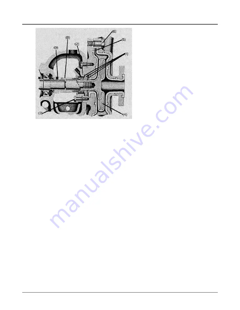
Figure 37:
(a-1) Place inner seal gasket, stationary seat, and outer seal gasket into stuffing box cover.
(a-2) Bold stuffing box cover to frame.
(a-3) Bolt gland to stuffing box cover. Tighten bolts evenly.
(a-4) Screw impeller on shaft until impeller butts firmly against shaft shoulder. Care should be taken not
to damage seal rotating assembly when installing impeller.
(a-5) Place casing gasket in casing.
(a-6) Bolt casing to stuffing box cover. Tighten bolts on alternate sides of casing so it does not cock.
Tighten snugly but do not over-tighten. Gap should be even at all points between casing and cover. Bolt
torque should be 18 to 20 ft. lbs.
(a-7) Adjust impeller as outlined in Impeller clearance adjustment.
(a-8) Slide drive collar and rotating assembly until it contacts stationary seat. Compress the rotating as-
sembly until the line of the thin metal disc which appears in the holes in the rotating assembly line up
with the lines scribed on the rotating assembly. Tighten set screws.
(a-9) Tighten set screw in deflector.
(a-10) Refer to Sept 8 for further instructions.
B. PTFE Bellows Seal
6.6 Reassembly of pump
44
3107 Installation, Operation and Maintenance Instructions


