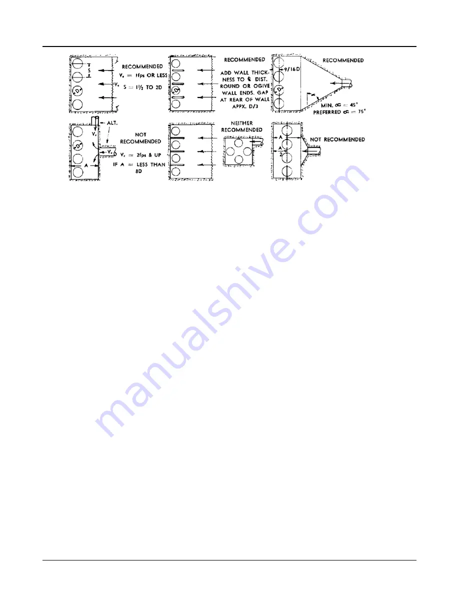
Figure 18:
The velocity of the water approaching the pump suction pipe should be kept to a maximum of one foot
per second to avoid air being drawn into the pump. Pump suction inlet velocities and submergence (the
height of the water above the pump inlet) are two additional factors that must be considered. These fac-
tors vary so greatly with the size and capacities of the individual pumps and systems that past experi-
ence, or a good reference, should be relied upon in arriving at these values.
The suction pipe should be sized to obtain a flow velocity of 4 to 7 feet per second. Changes in flow di-
rection should be avoided wherever possible, especially near the pump suction. A reducer at the pump
suction flange to smoothly accelerate and stabilize flow into the pump is desirable.
Refer to the nearest Goulds representative for further information.
Installations with pump above source of supply - suction lift
1.
Keep suction pipe free from air pockets - See Fig. 16.
2.
Piping should slope upwards from source of supply.
3.
No portion of piping should extend above the pump suction nozzle.
4.
All joints must be air tight.
Installations with pump below source of supply - suction head or flooded suction
1.
A gate valve should be installed in the suction line to permit closing of the line for pump inspec-
tion and maintenance.
2.
Keep suction pipe free from air pockets.
3.
Piping should be level or slope gradually downward from the source of supply.
4.
No portion of the piping should extend below pump suction flange.
5.
The size of entrance from supply should be no smaller than the suction pipe.
6.
The suction pipe should be adequately submerged below the liquid surface at the source of sup-
ply.
2.9 Piping - discharge
1.
Gate and check valves should be installed in the discharge line. The check valve should be locat-
ed between the gate valve and pump to permit inspection of the check valve. The gate valve is
required for priming, regulation of flow and for inspection and maintenance of the pump. The
check valve is required to prevent reverse flow through the pump when the driver is turned off.
2.9 Piping - discharge
20
3107 Installation, Operation and Maintenance Instructions


