


www.ittcontrols.com
9
Model 581A Differential Pressure Switch
Section 2
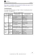
Section 2—Installation
The instrument should be inspected at time of unpacking to detect any dam-
age that may have occurred during shipment.
IMPORTANT: The DPU was checked for accuracy at the factory. Do not change any of
the settings during examination or accuracy could be affected.
For applications requiring special cleaning/precautions, a polyethylene bag
is used to protect the instrument from contamination. This bag should be
removed only under conditions of extreme cleanliness.
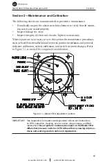
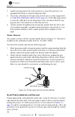
Mounting/Piping/DPU Installation
Mount the instrument with four 5/16" (8mm) bolts, Grade 5 or greater,
torqued to 17 ft/lbs (see Figure 7.1). Mounting structures should be designed
Response spectra at mounting surface of the instrument shall not exceed those
conduit shall be supported by the same mounting as the DP instrument base
in order to minimize relative motion of the DP instrument and connections.
Dimensional drawings are provided in
Section 5, page 32
.
See Appendix A for Model 199 DPU installation and maintenance informa-
tion.
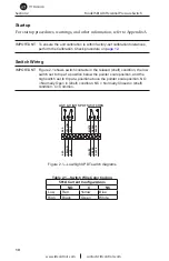
Electrical Connection
Units are supplied with dual alarm switches. The direct-set switch contacts
are adjustable over 10% to 90% of the scale range.
The high switch and low switch set point adjustment procedures are covered
in
Changing Switch Set Point, page 20
.
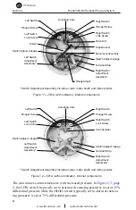
For physical location of switches, see Figures 1.1 and 1.2,
page 4
.
Switch Use
temperature, humidity, airborne contamination, vibration, amount of plunger
travel, cycling rate, and rate of plunger travel (and others), as well as by the
electrical (circuit) characteristics.
IMPORTANT: Arc suppression for inductive loads will prolong the life of the switch
contacts.


