www.ittcontrols.com
15
Model 581A Differential Pressure Switch
Section 3
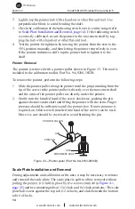
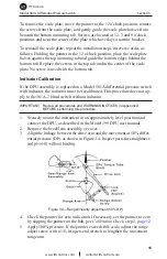
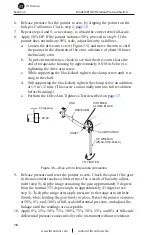
To remove the scale plate, move the pointer to the 12 o'clock position, remove
the screws from the scale plate, and gently guide the scale plate halves from
beneath the bottom mounting tab. Screws are located at 12, 3 and 9 o'clock
positions and near the center of the plate which overlays a narrow bracket.
To reinstall the scale plate, repeat the installation steps in reverse order, as
follows. Holding the pointer in the 12 o'clock position, place the scale plate
halves against the top mounting tab and guide the bottom edges behind the
bottom tab. Replace the screws in the top tab and in the center of the scale
plate. No screw is used with the bottom tab.
Indicator Calibration
If the DPU assembly is replaced on a Model 581A differential pressure switch
with indicator, the indicator must be recalibrated. This procedure does not ap-
ply to the 581A-2 blind switch without indicator.
IMPORTANT: Review all procedures and WARNINGS/NOTICES in Appendix A
BEFORE performing this procedure.
1. Securely mount the instrument in an approximately level position and
connect the DPU, as described in the Model 199 DPU user manual.
2. Remove the bezel/lens assembly or cover.
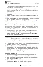
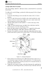
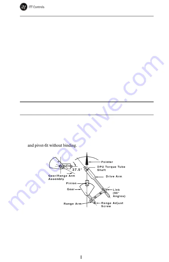
3. Align the linkage between the drive arm and the movement at 50% differ-
ential pressure (DP) as shown in Figure 3.4. Inspect parts for straightness
Figure 3.4—Range/linearity adjustment (50% DP)
4. Check the pointer for zero indication. If necessary, set the pointer to zero
by slipping the pointer on the hub, per
Calibration Check
, step 2,
page 12
.
5. Apply 100% pressure. If the pointer exceeds full-scale, adjust the range
adjust screw with a 1/8-in. open-end wrench to lengthen the movement
range arm.


