www.ittcontrols.com
4
Section 1
Model 581A Differential Pressure Switch
Left Switch
Right Switch
Pointer
Left Switch
Lock Screw
Plunger Screw
Actuating Cam
Left Switch
Adjustment
Assembly*
Switch Adjust Linkage
Plunger Screw
Right Switch
Lock Screw
Drive Arm
Stop Bracket
Movement Assembly
Terminal Strip
Switch Adjust Linkage
Right Switch
Adjustment
Assembly*
Range Adjust
* Switch Adjustment Assembly includes crank, index shaft, and index pointer.
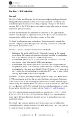
Figure 1.1—581A (with indicator), internal components
Left Switch
Right Switch
Left Switch
Lock Screw
Plunger Screw
Actuating Cam
Left Switch
Adjustment
Assembly*
Switch Adjust Linkage
Plunger Screw
Right Switch
Lock Screw
Terminal Strip
Switch Adjust Linkage
Right Switch
Adjustment
Assembly*
Cam Actuator
* Switch Adjustment Assembly includes crank, index shaft, and index pointer.
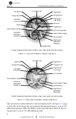
Figure 1.2—581A (without indicator), internal components
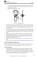
The cam rotates counterclockwise with increased pressure. In
Figure 1.3, page
5
, the LOW switch (typically set to alarm at decreasing pressure) is set at 25%
differential pressure while the HIGH switch (typically set to alarm at increas-
ing pressure) is set at 75% differential pressure.


