


MANUAL
#
OMP
L80
‐
P
REV.
6
INTRODUCTION
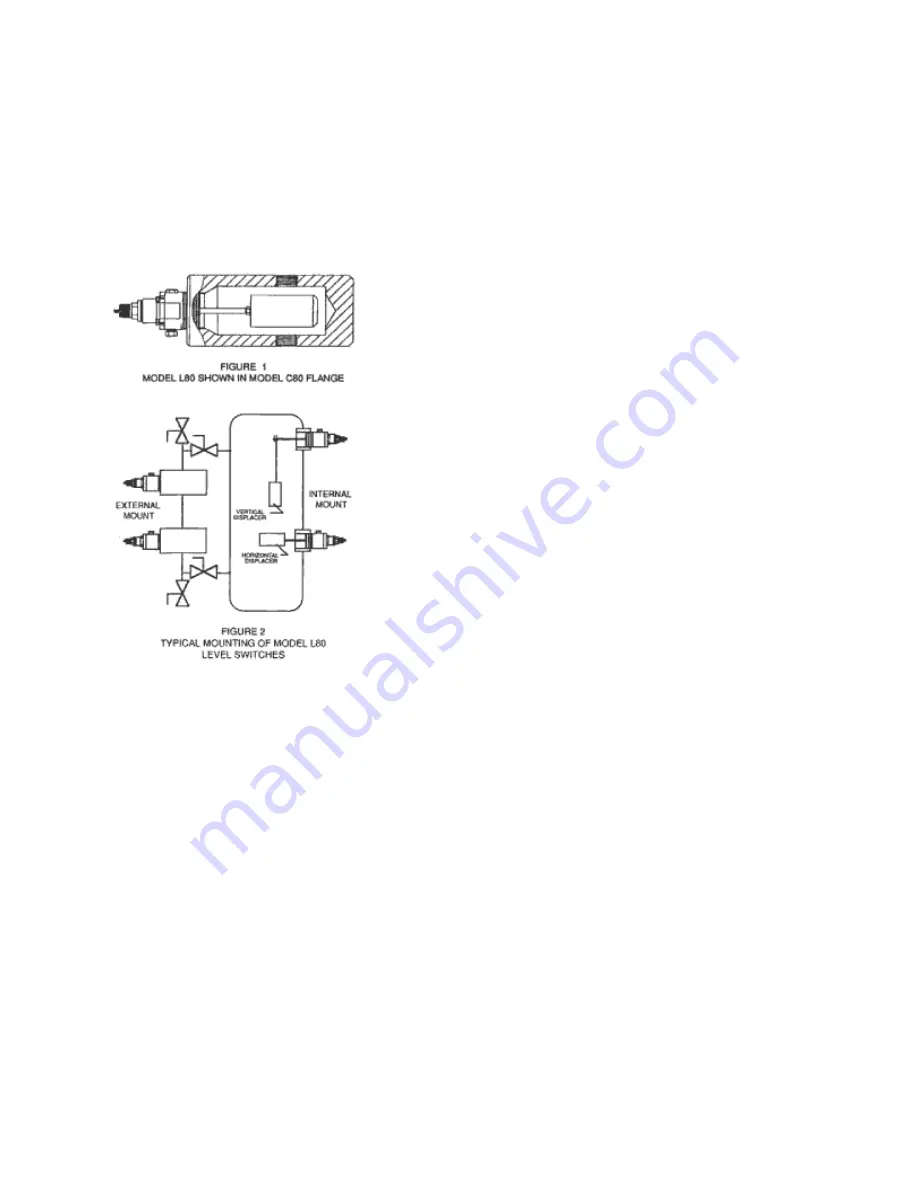
The
K
‐
Dyne,
Inc.
electric
version
of
the
Model
L80
is
a
2"
NPT
mounted
liquid
level
switch.
It
is
typically
mounted
in
a
K
‐
Dyne
Model
C80
cage
shown
in
the
figure
1
for
external
bridle
mounting
or
may
be
internally
mounted
in
a
2"
NPT
(F)
connection.
Both
mounting
configurations
are
shown
in
figure
2.
These
sensors
send
or
remove
an
electric
signal
when
a
liquid
in
a
tank
or
a
pressurized
vessel
reaches
a
predetermined
level.
The
L80
operation
mode
as
either
a
low
(direct)
or
high
(reverse)
acting
level
switch
is
selected
by
rotating
the
pivot
body
180
˚
.
Selection
of
N.O.
or
N.C.
switching
depends
upon
the
wiring
configuration
utilized.
Both
SPDT
or
DPDT
snap
acting
dry
contacts
offered
with
the
switch
are
U.L.T
rated
for
hazardous
locations.
2.0
PRINCIPLE
OF
OPERATION
(Refer
to
Figure
3)
The
electric
version
of
the
K
‐
Dyne,
Inc.
Model
L80
2"
NPT
mounted
liquid
level
switch
is
a
multi
‐
functional
pneumatic
liquid
level
sensor.
Depending
on
the
mode
of
operation,
it
functions
as
a
three
way,
normal
closed
(N.C.)
or
normally
open
(N..O.)
electric
switch
that
will
operate
when
the
liquid
level
rises
or
falls
below
a
fixed
point
in
a
tank
or
pressurize
vessel.
Type
of
voltage
may
be
A.C.
or
D.
C.
and
the
maximum
amperage
depends
on
the
amount
of
voltage
used.
Consult
the
data
sheet
of
the
specific
switch
being
used
for
the
switch
rating.
The
switch
senses
a
change
in
the
buoyancy
of
a
displacer
assembly
(9)
inside
either
a
pressurized
or
an
unpressurized
vessel.
A
pivoting
action
is
used
to
transmit
the
buoyancy
change
of
the
displacer
assembly.
The
bore
of
the
cone
(14)
contacts
a
pivot
(13)
on
the
pivot
body
(3).
The
o
‐
ring
(8)
provides
a
pressure
tight
seal
between
he
body
(7)
and
the
shaft
of
the
cone
protruding
through
the
o
‐
ring.
Pressure
in
the
vessel
acting
on
the
shaft
of
the
cone
forces
the
cone
against
the
pivot.
The
position
of
the
pivot
point,
at
the
center
of
the
o
‐
ring,
allows
the
displacer
assembly
to
move
vertically
with
the
liquid
level.
This
motion
is
guided
to
act
along
the
axis
of
the
transverse
rod
(16)
by
two
vertical
tabs
on
the
pivot
body
that
mate
with
notches
in
the
cone.
Any
vertical
motion
of
the
displacer
is
transmitted
by
the
cone
to
the
ends
of
the
transverse
rod.
A
ramp
on
the
outside
diameter
of
the
transverse
rod
contacts
the
tip
of
the
push
rod
(17)
to
operate
the
lever
on
the
switch
assembly
(2).
2.1
LOW
OPERATION
For
use
as
a
low
‐
level
sensor
(output
on
rising
level),
the
pivot
body
(13)
is
positioned
with
the
enlarge
end
of
the
transverse
rod
(16)
up
towards
the
spring
cap
(4).
The
displacer
assembly
weight
exerts
a
clockwise
rotational
force
on
the
cone
through
the
pivot.
The
spring
(5),
acting
through
he
spring
guide
(6)
exerts
a
counterclockwise
rotational
force
on
the
cone.
When
the
liquid
level
is
below
the
displacer
assembly,
the
clockwise
force
is
greater.
This
force
causes
the
cone
to
push
upward
against
the
transverse
rod
allowing
the
tip
of
the
push
rod
to
be
positioned
away
from
the
switch
assembly
lever.
In


