User Guide
19
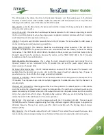
The ICC module is the cabinet interface to the Camera Processor unit. It provides power to the Camera
Processor unit and receives video and data. It places the detection calls in the detector rack or input file. The
following section defines some of the features of the ICC module.
Menu Button - press the Menu button for two seconds and then release it to bring up the System Menu Bar
on the monitor video overlay.
Green On Line LED - this indication should always be illuminated when the ICC module is operating. Failure of
the On Line LED to illuminate, when the proper power is applied, indicates a problem with the ICC module
and it should be sent in for evaluation and repair.
USB Port - this port is used for USB communications to the ICC module. This is also where the USB mouse is
connected during setup and programming operations.
Yellow Video In Ok LED - this indication should be on solid during normal operation. If this LED fails to
illuminate or blinks after the power and other wire terminations have been made, re-check the cabling
terminations. If the VIDEO IN OK LED still fails to illuminate or blinks, contact your local Iteris Dealer or Iteris
Product Support Team for assistance. Also see the section on the VIDEO IN OK LED in the ICC module
installation section for more information.
Multi Cable Wire Pair Terminations - this is where the multi conductor cable wire pairs coming from the
Camera Processor unit are terminated to the ICC module. One pair each for power output, video, and
communication - three pair total.
AC Power Wire Terminations - the ICC module requires a source of 120 VAC power. If AC power is not
available from the detector rack on pins L, M, and N then power should be hooked up here. If power is
provided on pins L, M, and N, the front plug is automatically disabled.
Channel 1 & 2 Call LEDs - these indicators should illuminate when calls are being placed to the outputs of the
ICC module. They represent open collector outputs triggered by the detection zone that the channel it is
associated with.
Channel 1 & 2 Test Switches - these toggle switches have three positions. The default position is in the middle
and is the position they should be kept in during normal operation. The switch can be manually pushed up to
place a momentary call (contact closure) on the output channel or can be pushed down to place a constant
call on the output channel for testing or troubleshooting purposes. When you are done testing, be sure to
restore the switch to the middle position for normal operation.
RS-232 Port - this serial port is used to communicate with the ICC module via RS-232. This port would
normally be used for firmware upgrades using the Vantage Software Upgrade (VSU) program to upgrade the
VersiCam firmware. This port can also be used for direct connection with the Vantage Remote Access
Software (VRAS).
BNC Video Out - this is the video output from the ICC module. This is where the user would hook up a video
monitor during setup and programming to see the Camera Processor unit output video and video overlay.
Содержание VersiCam
Страница 1: ...Part Number 493432201 Rev F ...
Страница 13: ...User Guide 13 2 1 Menu Tree ...
Страница 30: ...User Guide 30 ...
Страница 77: ...User Guide 77 10 TECHNICAL INFORMATION IMSA 39 2 40 2 Cable ...
Страница 79: ...User Guide 79 VersiCam Specification Sheet ...
Страница 80: ...User Guide 80 Phase Information ...
Страница 81: ...User Guide 81 Detector Rack Configurations ...
Страница 83: ...User Guide 83 ...
Страница 84: ...1700 Carnegie Avenue Santa Ana CA 92705 Phone 949 270 9400 Fax 949 270 9401 ...


