User Guide
17
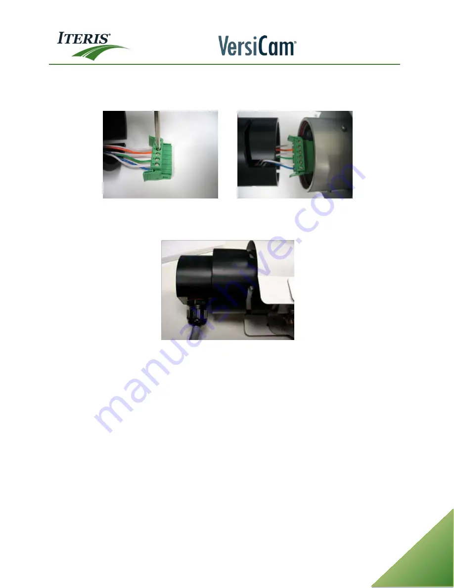
Terminate the wires to the Camera Processor unit connector plug as shown. Be sure to observe the
connector orientation. Insert each wire into the correct slot on the Camera Processor unit connector plug.
Secure each wire in place by tightening down each screw using a small flat blade screwdriver.
Connect Wires to Connector Plug Wired Connector Plug in Place
Plug the connector plug into the socket on the back of the Camera Processor unit housing, it is keyed so you
can only plug it in one way.
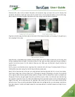
Cap Assembly Re-Installed
Align the slots in the (black) cap assembly with the three posts on the Camera Processor unit housing. Grip
the cap assembly firmly and push it into place. When the two posts are fully seated, give the cap assembly a
quarter turn to fully secure it to the Camera Processor unit. When you are finished it should look like the
picture above.
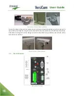
Pull the camera sun shield back and snug down the camera bracket set screws. Final adjustment of the sun
shield will be done later during the Field of View (FOV) setup procedure.
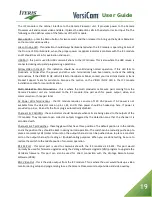
Mount the camera bracket to the pole arm using stainless steel banding material. Do not use hose clamps,
they tend to loosen over time and may result in the camera moving and slipping on the pole. The luminare
arm or signal mast arm are typical mounting locations. Choose a location where the camera is centered over
the approach and has enough height to avoid cross traffic occlusion. A five or six foot extension bracket may
be required on signal mast arms to obtain acceptable height. Though some luminare arms will provide good
height, they may not be centered over the approach and if they are too far to one side can also create
occlusion issues. If you are still unsure about the best camera mounting location, you can always contact your
local Iteris Dealer or call Iteris Product Support for recommendations on optimal camera mounting for your
application.
Содержание VersiCam
Страница 1: ...Part Number 493432201 Rev F ...
Страница 13: ...User Guide 13 2 1 Menu Tree ...
Страница 30: ...User Guide 30 ...
Страница 77: ...User Guide 77 10 TECHNICAL INFORMATION IMSA 39 2 40 2 Cable ...
Страница 79: ...User Guide 79 VersiCam Specification Sheet ...
Страница 80: ...User Guide 80 Phase Information ...
Страница 81: ...User Guide 81 Detector Rack Configurations ...
Страница 83: ...User Guide 83 ...
Страница 84: ...1700 Carnegie Avenue Santa Ana CA 92705 Phone 949 270 9400 Fax 949 270 9401 ...


