94
9.4
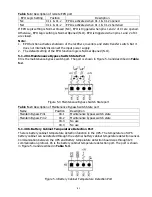
Parallel Cable Connection
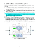
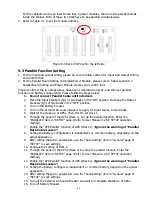
There are two connectors at the end of Parallel Cable, one is 16-pins and the other is 2-pins. Insert
the 16-pins connector into the CN7 and 2-pins connector into the CN10. Both racks use the same
way to connect the parallel cable. Please refer to connector's position as shown in figure 9-4 & 9-5
below.
For the cabinet with two parallel boards, please insert the connectors into any one of two boards.
Figure 9-4 Rack 1 Parallel Board
Figure 9-5 Rack 2 Parallel Board
Warning:
The parallel cable of each UPS must to be connected correctly, the wrong connection
will cause the UPS system cannot operate normally.
9.5
Parallel System Turn On Procedure
1
Please make sure the section 9.1 ~ 9.4 has been well followed.
2
Please confirm the Input breaker and output breakers of each UPS (Rack) have already been
turned “ON”.
3
Turn On the battery Breaker.
4
Turn on the external AC source breaker to apply AC Input source to two Racks.
5
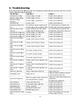
Through the panel of the UPS 1(Rack 1) or UPS 2(Rack2), set up the total power module
number and redundant number. (Refer to User Manual 4.2.6 SETUP Screen).
6
Through the panel of the UPS 1(Rack 1) or UPS 2(Rack2), get all module information , and
confirm the information of all module can be display on the panel.( Refer to User Manual 4.2.5
MEASUREMENT Screen)
7
Please confirm the system without any abnormal event through the panel display.(Refer to
User Manual 4.2.8 EVENTS Screen)
8
Turn on the UPS through the ON switch or control page of the panel. (Refer to User Manual
4.2.4 Control Screen)
Содержание F22 Online UPS
Страница 1: ...F22 Online UPS For 30KW Power Module Uninterruptible Power Supply System Version 4 0 User Manual ...
Страница 18: ...15 Figure 2 14 Standard Series 42U Terminal Blocks Figure 2 15 Extended Series 42U Terminal Blocks ...
Страница 25: ...22 ...
Страница 57: ...54 Figure 4 6 Control menu Figure 4 7 Control screen page 1 Figure 4 8 Control screen page 2 ...


