93
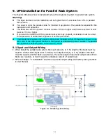
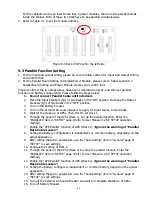
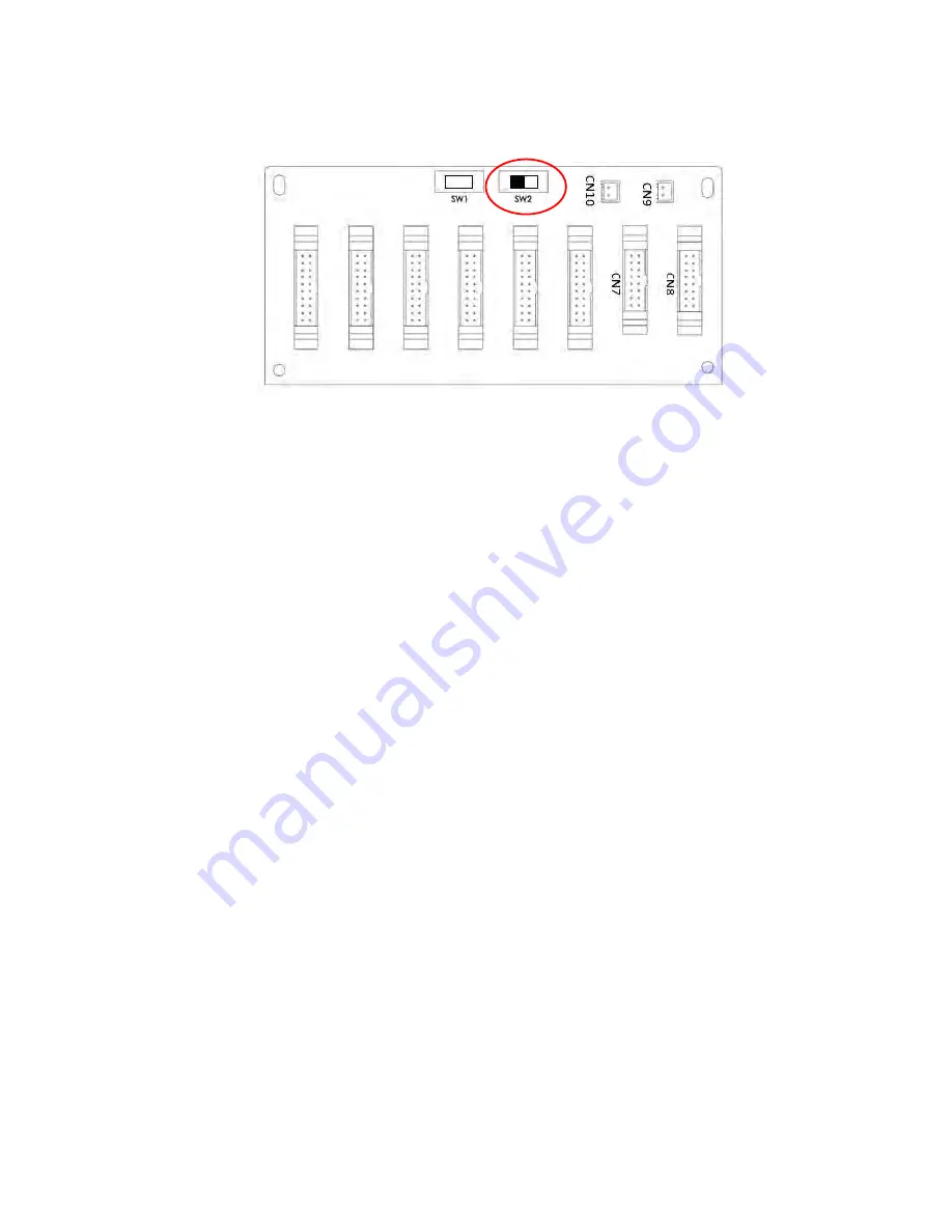
For the cabinets which can insert more than 5 power modules, there are two parallel boards
inside the cabinet. Both of these two SW2 have to be adjusted simultaneously.
2.
Refer to Table 2-1 to set the module address.
Figure 9-3 Rack 2 SW2 set to the left side
9.3 Parallel Function Setting
1.
For the input and output wiring, please be sure to follow section 9.1 Input and Output Wiring
and confirm that.
2.
For the Parallel Board Setting and Install Power Module, please sure to follow section 9.2
Parallel Board Setting and Power Module process and confirm that.
Please confirm if the two steps above have been completed correctly, and then set parallel
function and Battery configuration. Please follow the steps below:
1.
Do not connect Parallel Cable until informed.
2.
Place the Input breakers (Q1) of two Racks in the “ON” position. But keep the Output
breakers (Q3) of two Racks in the “OFF” position.
3.
Turn on the battery breaker.
4.
Turn on the external AC source breaker to apply AC Input source to two Racks.
5.
Wait for the wake-up of UPSs. Then start to set Rack 1.
6.
Through the panel of the UPS 1(Rack 1), set up the parallel function. Enter the
“PARALLEL” item in “SETUP” page. (Refer to User Manual 4.2.6.5 SETUP operation
method)
7.
Enable the “UPS Parallel” function of UPS 1(Rack 1). (
Ignore the warning of “Parallel
Rack Cable Loosen”
)
8.
Setting the Battery configuration is independent or common battery, depending on the
actual application.
9.
After setting these two parameters, use the “Save Setting” item in “General” page of
“SETUP” to save settings.
10.
Continue the setting of Rack 2.
11.
Through the panel of the UPS 2(Rack 2) to setup the parallel function. Enter the
“PARALLEL” item in “SETUP” page. (Refer to User Manual 4.2.6.5 SETUP operation
method)
12.
Enable the “UPS Parallel” function of UPS 2(Rack 2). (
Ignore the warning of “Parallel
Rack Cable Loosen”
)
13.
Setting the Battery configure is independent or common battery, depend on the actual
application.
14.
After setting these two parameters, use the “Save Setting” item in “General” page of
“SETUP” to save settings.
15.
Turn off the external AC Source Breaker and wait for complete shutdown of UPSs.
16.
Turn off Battery Breaker.
Содержание F22 Online UPS
Страница 1: ...F22 Online UPS For 30KW Power Module Uninterruptible Power Supply System Version 4 0 User Manual ...
Страница 18: ...15 Figure 2 14 Standard Series 42U Terminal Blocks Figure 2 15 Extended Series 42U Terminal Blocks ...
Страница 25: ...22 ...
Страница 57: ...54 Figure 4 6 Control menu Figure 4 7 Control screen page 1 Figure 4 8 Control screen page 2 ...


