


79
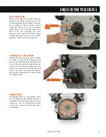
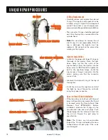
Position Crankshaft for Rocker Removal
• Special Tool ZTSE4697 can be used to
service the rocker arms, valve bridges or
push rods. Rotate the crankshaft until the
vibration damper dowel pin is in the twelve
o'clock position. Wiggle the rocker arms
for number 1 cylinder. If the rockers do not
move freely, rotate the crankshaft one
complete revolution. The rockers should
now be loose on number 1 cylinder.
Cylinders number 1, 2 and 4 can now be
serviced. Rotate the crankshaft one
revolution to service cylinders 3, 5 and 6.
Installing Spring Compressor Base
• Remove the injector of the cylinder to be
serviced. Insert the injector's hold-down
clamp into the base of tool. Install the
assembly as if installing an injector. Snug
the hold-down bolt but do not torque.
•
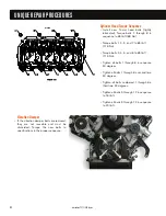
Note:
Use clean shop towels to plug any oil
drain holes before removing any components.
UNIQUE REPAIR PROCEDURES
International
®
VT 275 V6 Engine
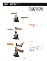
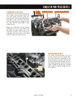
Compressor Plate
• Install the valve spring compressor plate
on top of the valve bridges. With the plate
in position, install the compressor bolt.
Turn the bolt with a hand wrench until the
plate contacts the top of the base. The
rocker arms may now be removed. If the
valve bridges must be serviced, back out
the compressor bolt and remove the plate
to gain access. Reinstall the rocker arms
using the compressor tool.
• Caution:
Be careful not to drop the rocker
arm ball into the engine.
D
DO
OW
WEELL P
PIIN
N H
HO
OLLEE
Содержание VT 275 V6
Страница 1: ...VT 275 V6 ENGINE model year 2005...
Страница 4: ...4...
Страница 110: ...110 International VT 275 V6 Engine NOTES...
Страница 111: ...111 International VT 275 V6 Engine NOTES...
Страница 112: ...2005 INTERNATIONAL TRUCK AND ENGINE CORPORATION TMT 120502 PRINTED IN THE U S A...


