

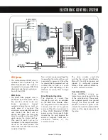


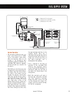


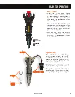


System Operation
• The fuel pump, fuel heater, pressure
relief valve, Water-in-Fuel (WIF)
sensor, recirculation valve, water
drain and primary filter are all
located in the Horizontal Fuel
Conditioning Module (HFCM). The
secondary filter, pressure regulator
and banjo bolts are mounted on
the engine.
• The ECM uses the fuel pump relay
to activate the fuel pump at key-on.
Fuel drawn from the tank contacts
the electric fuel heater, passes
through the one-way check valve,
and enters the filter where water is
separated. Fuel passes through the
filter media and enters the pump
inlet while water settles to the
bottom of the housing until the level
of water activates the WIF sensor.
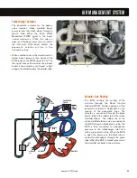
Pressurized fuel from the pump is
routed to the engine-mounted filter.
Fuel flows through the filter, then
through individual steel lines to the
cylinder heads. Each line is
attached to the cylinder head with a
banjo bolt. Each bolt contains an
orifice and a check valve. Once in
the head passages, fuel is
distributed to the injectors.
• Fuel is exposed to the pressure
regulator in the secondary filter
housing. The regulator returns
excess fuel to the HFCM where it is
directed to either the fuel tank or
the pump inlet, depending on fuel
temperature.
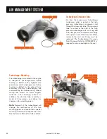
• Both filter elements push open a
fuel passage valve when inserted
into their respective housings.
Without the filter in place, fuel will
not flow through the system. The
engine could start without the filter,
but will not run properly.
Secondary fuel filter
HFCM
Cylinder heads
Fuel tank
Fuel injectors
Drilled passage
Check valve in
banjo bolt
Fuel pressure
test port
Check valve in
banjo bolt
Drilled passage
Fuel return from
engine to HFCM
Fuel supply
to engine
Fuel return
to tank
Fuel supply
to HFCM
Unfiltered fuel from the fuel tank
Conditioned fuel from HFCM to fuel filter
Conditioned fuel from fuel filter
Primary fuel filter
FUEL SUPPLY SYSTEM
49
International
®
VT 275 V6 Engine
Содержание VT 275 V6
Страница 1: ...VT 275 V6 ENGINE model year 2005...
Страница 4: ...4...
Страница 110: ...110 International VT 275 V6 Engine NOTES...
Страница 111: ...111 International VT 275 V6 Engine NOTES...
Страница 112: ...2005 INTERNATIONAL TRUCK AND ENGINE CORPORATION TMT 120502 PRINTED IN THE U S A...


