


ECM
BATTERY
200 A
IAH
RELAY
GLOW PLUG
RELAY
GP
C
GP
D
GLOW PLUGS
ECT
STARTER
IAH
BAP
X1-17 GPC
X1-21 GPD
24 6
13 5
4
12-WAY
ENGINE TO CHASSIS
CONNECTOR
N.O. TERMINAL
X1
X2
X3
X4
X1
X2
X3
X4
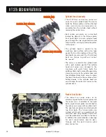
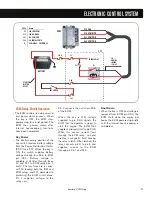
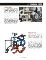
Glow Plug System
• The VT 275 uses glow plugs to aid
cold starts. The ECM turns on the
glow plugs prior to engine cranking
to increase the temperature of the
cylinders. Glow plug operation is
controlled by the ECM through the
glow plug relay. The glow plugs
have full voltage if battery voltage is
normal, or pulse width modulated to
control the current if battery voltage
is above normal.
The ECM calculates glow plug on-
time based on coolant temperature
and barometric pressure. The
required time to warm up the
cylinders decreases as engine
coolant temperature increases.
Warm up time decreases as
barometric air pressure increases.
The glow plugs may continue to be
energized after start-up to
reduce emissions.
Relay Operation
• The glow plug relay receives battery
voltage to its common terminal from
the starter power-feed terminal. The
normally open terminal connects to
the individual glow plugs through
the glow plug harness. One end of
the relay coil is always grounded
through pin 4 of the engine 12-way
connector. The ECM supplies 12
volts to the other end of the coil
through ECM pin X1-17 in order to
close the relay contacts.
Glow Plug Lamp
• The glow plug lamp is used as a
wait-to-start indicator. The ECM
lights the glow plug lamp at glow
plug activation to signal the
operator to wait for the cylinders to
warm up.
• Both lamp operation and the glow
plug operation are based on BAP
and ECT values but are independ-
ent of each other.
• The glow plug operation may
continue after the lamp is off.
Glow Plug Diagnostics
• Glow plug diagnostics are used to
determine if the relay is operating
correctly when commanded on. An
additional wire on the relay's
normally open terminal connects to
ECM pin X1-21. This circuit, GPD,
allows the ECM to monitor the
relay operation.
• The glow plugs can be turned on
using the KOEO Glow Plug/Inlet
Air Heater Test. The test can only
be activated twice per key cycle.
ELECTRONIC CONTROL SYSTEM
32
International
®
VT 275 V6 Engine
Содержание VT 275 V6
Страница 1: ...VT 275 V6 ENGINE model year 2005...
Страница 4: ...4...
Страница 110: ...110 International VT 275 V6 Engine NOTES...
Страница 111: ...111 International VT 275 V6 Engine NOTES...
Страница 112: ...2005 INTERNATIONAL TRUCK AND ENGINE CORPORATION TMT 120502 PRINTED IN THE U S A...


