

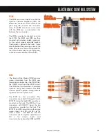


IDM
ECM
X1
X2
X3
X4
ED
C
B
A
MAF / IAT
EGR
DRIVE
MODULE
BCS
IPR
EGR
VALVE
RIGHT BANK INJECTORS
X1-7 IAT
X1-6 IAT SIG GRD
X2-2 MAF
LEFT BANK INJECTORS
FIXED
RESISTOR
HEATED
ELEMENT
FIXED
RESISTOR
THERMISTOR
MAF
ECM
VREF
SIG
GRD
MICRO-
PROCESSOR
4
9
ENGINE
IN-LINE 12-WAY
CONNECTOR
ACT GRD
KEY PWR
MAF
SIG
NAL
KEY
P
O
WE
R
AC
TUA
TOR
GR
D
SIG
N
AL
GR
D
IA
T
B+
B+
SIGNAL
CONTROL
X1
X2
X3
X1
X2
X3
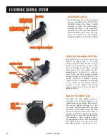
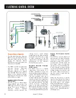
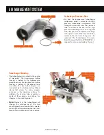
Mass Air Flow (MAF) Sensor
• The MAF sensor is used to measure
the mass of the fresh air portion of
the intake air charge. To reduce
Oxides of Nitrogen (NOx), a portion
of the fresh air charge is displaced
with cooled exhaust gases.
The ECM calculates the total
engine gas flow based on MAT,
MAP and RPM. The ECM then
determines the required EGR
percent based on the current
engine operating conditions. At this
point, the ECM commands the
exhaust portion of the total charge
through the EGR valve while
monitoring the fresh air portion
through the MAF sensor.
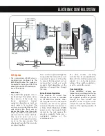
Sensor Construction
• The sensor housing contains two
sensors, the MAF sensor and the
Intake Air Temperature (IAT) sensor.
The MAF sensor contains a heated
element placed in the air stream.
The amount of electrical power
needed to maintain the element at
the proper temperature depends
directly on the mass of air moving
over the element.
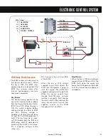
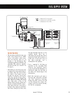
Sensor Operation
• The MAF sensor is made up of two
voltage divider circuits. A thermistor
and a fixed resistor make up one
voltage divider circuit, and the
heated element and a fixed resistor
make up the other voltage divider
circuit. The two voltage divider
circuits are combined into a bridge
circuit with a common power supply
and a common ground.
• During operation, when voltage is
applied to the bridge, the
temperature of the heated element
increases and the resistance
decreases. This affects the output
of the divider circuit.
The thermistor side is affected only
by ambient air temperature. The
divider voltages are compared and
the input voltage to the bridge is
increased or decreased until both
divider voltages are equal.
An increase or decrease in airflow
will change the ratio between the
divider voltages, which results in a
change to the supply voltage.
The signal controller circuit
measures the voltage to the bridge
and, based on that value, sends a
frequency signal to the ECM. The
correct key-on, engine-off
frequency is 400+100 Hz.
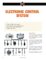
ELECTRONIC CONTROL SYSTEM
34
International
®
VT 275 V6 Engine
Содержание VT 275 V6
Страница 1: ...VT 275 V6 ENGINE model year 2005...
Страница 4: ...4...
Страница 110: ...110 International VT 275 V6 Engine NOTES...
Страница 111: ...111 International VT 275 V6 Engine NOTES...
Страница 112: ...2005 INTERNATIONAL TRUCK AND ENGINE CORPORATION TMT 120502 PRINTED IN THE U S A...


