


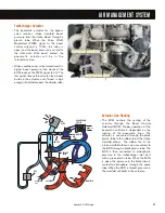


System Operation
• The VT 275 uses a regulated two-
stage turbocharger to boost the
volume of air flowing into the
cylinders. The system consists of
two turbochargers with exhaust
flow through the units controlled by
the turbocharger boost control
solenoid. The smaller of the two
turbochargers is identified as the
high-pressure turbocharger and is
sized to provide boost for low to
medium speeds. The larger
turbocharger is the low-pressure
turbo and is sized to work in tandem
with the high-pressure unit to
provide the boost and air flow
needed for high-speed, high-load
engine conditions.
• Air passes through the air filter
element and the mass air flow
sensor to enter the compressor of
the low-pressure turbocharger. Air
that leaves the low-pressure
compressor flows through the
crossover tube to the compressor
inlet of the high-pressure turbo-
charger. Air from the compressor
goes to the Charge Air Cooler (CAC).
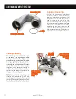
• The CAC is mounted in front of the
radiator. The cooler is an air-to-air
heat exchanger that uses airflow to
remove heat energy from the
pressurized intake charge. Re-
ducing the temperature of the air
increases the charge density, which
results in a more efficient engine
with quicker engine response and
reduced emissions.
• After the CAC, the air flows through
piping to the intake manifold where
it is distributed to the cylinders.
• Exhaust flow from the cylinders
exits the exhaust manifolds and
spools up the high-pressure turbine.
The exhaust passes through the
high-pressure turbine and enters
the low-pressure turbine. The
exhaust gases then exit the turbine
and flow out the exhaust system.
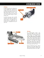
• A bypass valve controls the exhaust
flow through a passage that allows
a portion of the exhaust to bypass
the high-pressure turbine and go
directly to the low-pressure turbine.
Part of the exhaust gas that leaves
the left bank exhaust manifold is
diverted to the EGR cooler. Heat
energy is removed from the exhaust
while in the cooler and transferred
to the engine's coolant. The cooled
exhaust gases then flow through a
short internal passage in the intake
manifold to the EGR valve. The
EGR valve meters a portion of the
cooled exhaust gases into the
intake manifold where the exhaust
displaces a portion of the fresh
air charge.
AIR MANAGEMENT SYSTEM
41
International
®
VT 275 V6 Engine
LLO
OW
W P
PR
REES
SS
SU
UR
REE
LLO
OW
W P
PR
REES
SS
SU
UR
REE
C
CO
OM
MP
PR
REES
SS
SO
OR
R IIN
NLLEETT
C
CO
OM
MP
PR
REES
SS
SO
OR
R IIN
NLLEETT
IIN
NTTAAK
KEE M
MAAN
NIIFFO
OLLD
D
IIN
NTTAAK
KEE M
MAAN
NIIFFO
OLLD
D
LLO
OW
W P
PR
REES
SS
SU
UR
REE
LLO
OW
W P
PR
REES
SS
SU
UR
REE
TTU
UR
RB
BIIN
NEE O
OU
UTTLLEETT
TTU
UR
RB
BIIN
NEE O
OU
UTTLLEETT
EEX
XH
HAAU
US
STT TTU
UB
BEE AAS
SS
SEEM
MB
BLLYY
EEX
XH
HAAU
US
STT TTU
UB
BEE AAS
SS
SEEM
MB
BLLYY
FFR
RO
OM
M C
CH
HAAR
RG
GEE AAIIR
R C
CO
OO
OLLEER
R ((C
CAAC
C))
FFR
RO
OM
M C
CH
HAAR
RG
GEE AAIIR
R C
CO
OO
OLLEER
R ((C
CAAC
C))
EEG
GR
R VVAALLVVEE
EEG
GR
R VVAALLVVEE
B
BO
OO
OS
STT C
CO
ON
NTTR
RO
OLL S
SO
OLLEEN
NO
OIID
D
B
BO
OO
OS
STT C
CO
ON
NTTR
RO
OLL S
SO
OLLEEN
NO
OIID
D
P
PN
NEEU
UM
MAATTIIC
C AAC
CTTU
UAATTO
OR
R
P
PN
NEEU
UM
MAATTIIC
C AAC
CTTU
UAATTO
OR
R
C
CO
OM
MP
PR
REES
SS
SO
OR
R O
OU
UTTLLEETT TTO
O
C
CO
OM
MP
PR
REES
SS
SO
OR
R O
OU
UTTLLEETT TTO
O
C
CH
HAAR
RG
GEE AAIIR
R C
CO
OO
OLLEER
R ((C
CAAC
C))
C
CH
HAAR
RG
GEE AAIIR
R C
CO
OO
OLLEER
R ((C
CAAC
C))
Содержание VT 275 V6
Страница 1: ...VT 275 V6 ENGINE model year 2005...
Страница 4: ...4...
Страница 110: ...110 International VT 275 V6 Engine NOTES...
Страница 111: ...111 International VT 275 V6 Engine NOTES...
Страница 112: ...2005 INTERNATIONAL TRUCK AND ENGINE CORPORATION TMT 120502 PRINTED IN THE U S A...


