


ELECTRONIC CONTROL SYSTEM
37
International
®
VT 275 V6 Engine
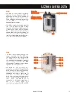
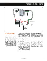
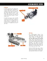
EGR System
• The motor-actuated EGR valve is
controlled and monitored by the
EGR Drive Module. The module is
connected to the engine CAN 2 link
allowing bi-directional communica-
tion with the ECM.
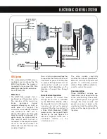
EGR Valve
• The EGR Valve poppet stem is
positioned by a three-phase motor.
The armature of the motor has
twelve permanent magnet
segments alternating as north or
south poles of a magnet. The
armature is surrounded by nine field
coils divided into three sets or
phases. Each phase has three coils
wired in parallel and spaced 120°
apart around the motor armature.
One lead of each coil set is
connected to the respective motor
circuit on the drive module. The
other leads from all of the nine coils
are joined together.
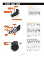
Two coil sets are powered together
to reposition the motor, with one set
connected to power and the other
to ground. Each powered coil set
creates either a north or a south
magnetic field depending on the
direction of current flow through
the coils.
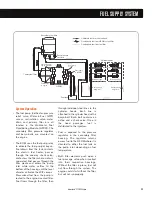
Drive Module Operation
• The direction of current flow
through the coil sets is controlled
by the EGR Drive Module. When
the integrated circuit in the module
connects one coil set to ground,
and one of the other two coil sets to
a Pulse Width Modulated (PWM)
power source, the magnetic fields
created by the coils oppose the
armature magnetic fields and a
controlled rotation of the
armature occurs.
The drive module constantly
switches the coil sets (identified as
Motor W, V, and U) from power and
ground to continually produce
rotation. Pulse width modulation is
used to control the current.
Communication
• Three Hall-Effect sensors are
located on a circuit board at the top
of the valve housing. The sensors
are supplied power and ground
through the drive module and
produce a series of signals so the
module can track the rotation of the
motor and the opening position of
the valve.
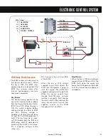
IDM
ECM
EGR DRIVE
MODULE
X1
X2
X3
X4
X1
X2
X3
X1
X2
X3
X4
X1
X2
X3
5
2
3
4
1
6
7
8
16
X2-13
X3-31
X2-6
X2-12 SHD
X3-30
WV
U
SENSOR GRD
POSITION SENSOR W
POSITION SENSOR V
POSITION SENSOR U
SENSOR 5V SUPPLY
SHIELD DRAIN
MOTOR W
MOTOR V
MOTOR U
CAN2-
CAN2+
GRD
ACT PWR
15
14
13
12
11
10
9
8
7
6
5
4
3
2
1
EGR
VALVE
10
4
ENGINE IN-LINE
RELAY
TO ECM RELAY
‘NORMALLY OPEN’
TERMINAL
TO FRAME
GROUND
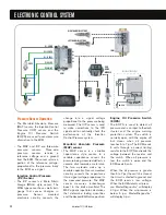
EGR DRIVE MODULE
EGR VALVE
POWER
GRD
POWER
GRD
S
S
S
S
S
S
N
N
N
N
N
N
Содержание VT 275 V6
Страница 1: ...VT 275 V6 ENGINE model year 2005...
Страница 4: ...4...
Страница 110: ...110 International VT 275 V6 Engine NOTES...
Страница 111: ...111 International VT 275 V6 Engine NOTES...
Страница 112: ...2005 INTERNATIONAL TRUCK AND ENGINE CORPORATION TMT 120502 PRINTED IN THE U S A...


