International HS 2.8L Скачать руководство пользователя страница 1

SERVICE MANUAL

International HS 2.8L

Содержание HS 2.8L

Страница 1: ...SERVICE MANUAL International HS 2 8L...

Страница 2: ...bad operation unauthorized adaptations unoriginal parts use or any other procedures that affect it way any Following the instructions and specifications of this manual the maintenance and repairing wi...

Страница 3: ...ration and Maintenance Recommendations 11 Cooling System 20 Fuel System 27 Lubrication System 41 Cylinder Head 47 Engine Block 63 Pistons and Connecting Rods 68 Crankshaft 76 Crankshaft Pulley 83 Engi...

Страница 4: ...3 International HS 2 8L 8120081 05 02 Service Manual INTERNATIONAL ENGINES SAFETY PRECAUTIONS...

Страница 5: ...hing if you do not know how to do it correctly Do not operate the engine in closed rooms because the exhaust gases are extremely prejudicial to the health Do not allow people or animals to stay close...

Страница 6: ...5 International HS 2 8L 8120081 05 02 Service Manual INTERNATIONAL ENGINES ENVIRONMENT...

Страница 7: ...been approved a program of actuation that includes activities as natural resources conservation elimination and residues recycling water protection noise reduction and acoustic isolation air purity co...

Страница 8: ...better performance to the vehicle also reduce noises and harmful gases emissions to the atmosphere Warning Any change in the fuel injection or air intake system or even the exhaust system may affect d...

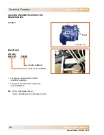
Страница 9: ...International HS 2 8L 8 Service Manual 8120081 05 02 INTERNATIONAL ENGINES TECHNICAL FEATURES...

Страница 10: ...Displacement 2 8 Liters Combustion System Direct Injection Rotation Sense front view Clockwise Firing Order 1 3 4 2 Opening Beginning 86 90 C Operation Temperature 86 102 C Lubricant oil Pressure at...

Страница 11: ...ENTIFICATION OF THE ENGINE NUMBER Location Identification B61 WG B60 VNT 536265 SERIAL NUMBER PARTS LIST NUMBER For engines manufactured in Brazil nr 000001 to 499999 For engines manufactured in Argen...

Страница 12: ...11 International HS 2 8L 8120081 05 02 Service Manual INTERNATIONAL ENGINES OPERATION AND MAINTENANCE RECOMMENDATIONS...

Страница 13: ...engine has been stayed inactive for a long period bleed the fuel system Key Positions 1 Off 2 Contact 3 Start Start Warning POSITION TRANSMISSION LEVER TO NEUTRAL 1 Position key in start position for...

Страница 14: ...gine in idle speed and transmission lever in neutral In turbocharged engines in order to do not damage the turbocharger shaft the engine must run during 30 thirty seconds under 1000 rpm before stopped...

Страница 15: ...ed Keep the engine operation temperature between 86 and 102 C 187 and 216 F engine Note It is operator responsibility the correct use of the product during the running in The not execution of the reco...

Страница 16: ...nd speed at maximum load Intake system Intake air temperature and restriction Fuel system circuit If the piping is unobstructed and free of vibrations extreme heat areas and leakages occurrences Exhau...

Страница 17: ...through the inspection lateral plug Check external belts conditions Cooling system check anti freezing replace at each 2 years Check oil fuel cooling piping conditions Replace external belts Replace t...

Страница 18: ...k done by the cylinders is positive in other words the cylinders spent a smaller amount of energy in the intake In turbocharged International HS 2 8L engine the turbocharger is also composed by a Wast...

Страница 19: ...Two belts equip the turbocharged International HS 2 8L engine It is very important that the belts be installed exactly as shown in the illustration Two tensors adjust automatically the belts tension e...

Страница 20: ...ved by a flexible rubber belt which must be replaced in predetermined intervals depending on the use conditions severity Follow strictly the specifications of belt tensor tightening guaranteeing its u...

Страница 21: ...International HS 2 8L 20 Service Manual 8120081 05 02 INTERNATIONAL ENGINES COOLING SYSTEM...

Страница 22: ...ake sure that the drainage hole is not obstructed 3 Remove radiator hoses from the engine and fan 4 Drain all the coolant water from the block 5 Check hoses condition and replace them if they are dama...

Страница 23: ...f clean water free of residues 7 Press radiator upper hose to help the air elimination and fill the system until only coolant water leaks free from bubbles through the thermostat housing hole Recommen...

Страница 24: ...ne at 2000 rpm approximately medium acceleration for five minutes F Increase speed up to 3500 rpm approximately 3 4 of the maximum acceleration for four minutes more G Slow down engine speed again to...

Страница 25: ...28 Nm WATER PUMP Removal 1 Drain cooling system 2 Remove radiator upper hose from the thermostat 3 Loosen fixation bolts of the power steering pump pulley 4 Loosen fixation bolts of the water pump pul...

Страница 26: ...g 3 Disconnect electric connections of the water temperature switch 4 Remove outlet elbow 5 Remove thermostat 6 Pay attention that the initial scale for the thermostat operation evaluation test is 88...

Страница 27: ...02 INTERNATIONAL ENGINES Note The preliminary specified test in this manual for the thermostat evaluation helps the diagnosis of a possible failure in the engine Therefore it is recommended to send th...

Страница 28: ...27 International HS 2 8L 8120081 05 02 Service Manual INTERNATIONAL ENGINES FUEL SYSTEM...

Страница 29: ...ore the volume reaches the minimum because sedimented impurities in the bottom of the tank can be suctioned damaging the filter Filling 1 Clean filling inlet duct cover whenever necessary 2 Every end...

Страница 30: ...F Fuel Filter The filter has the function to retain the impurities to make that the system receives a clean fuel avoiding this way damages in the engine fuel injection pump and the nozzles Note Use on...

Страница 31: ...clamp and install water in fuel sensor electric connection 1 and 4 4 Support filter in the support and if necessary adjust filter to allow better a position of the pipes 5 Install fuel inlet and outl...

Страница 32: ...s 5 Start and wait for 10 seconds to engine stabilization 6 If the engine doesn t start repeat the procedure starting from the item 2 It is recommended to change the fuel filter Avoid the lack of fuel...

Страница 33: ...close the bleeding point indicated 1 Open fuel filter upper plug 1 and loosen the 4 nozzle nuts 2 Crank engine until fuel drain through the filter upper plug and nozzles nut approximately 10 seconds 3...

Страница 34: ...ntil that center pin fits in the flywheel timing hole 10 Remove fuel injection pump inspection cover from timing housing cover complete with the gasket 11 Install the pin of the tool nr 8130633 in the...

Страница 35: ...einstallation 1 Remove pump plugs 2 Only for a new pump Install the tool pin nr 8130633 in the fuel injection pump turning the pump the necessary to introduce the pin Remove the limiter and tighten th...

Страница 36: ...ation 9 Connect boost control pipe and fix it with banjo bolt tightening it according to specification 10 Connect stop control solenoid wiring 11 Connect accelerator cable 12 Remove tool nr 8130633 13...

Страница 37: ...e and check system for leakages IDLE SPEEDADJUSTMENT 1 Check and adjust accelerator cable 2 Start engine and let it work until reach normal operation temperature always varying its speed 3 Using an ap...

Страница 38: ...ylinder head 5 Remove nozzle holders and discard copper washers 6 Protect fuel passages and nozzle pulverization holes Reinstallation 1 Check nozzles In case it is noticed any irregularity seek a Dist...

Страница 39: ...one copper washer under the head of the banjo bolt and two copper washers between the nozzle holder set and the banjo Tighten the banjo bolt according to specification 8 Install high pressure pipe ti...

Страница 40: ...not introduced in the hole b Turn slightly crankshaft enough to allow the timing pin fitting in the pump c Remove retention plate and lock pump d Loosen the three fixation bolts of the pump gear e Tur...

Страница 41: ...ERNATIONAL ENGINES 12 Assembly accelerator cable at fuel injection pump 13 Bleed fuel system See FUEL SYSTEM Bleeding 14 Install plug in housing tightening within of 22 to 28 Nm Note Remove special to...

Страница 42: ...41 International HS 2 8L 8120081 05 02 Service Manual INTERNATIONAL ENGINES LUBRICATION SYSTEM...

Страница 43: ...and check level twice to make sure of the check Complete the oil level only if the oil mark is below the dipstick lower mark the difference between the volume of the maximum mark and the minimum mark...

Страница 44: ...l filter see OIL FILTER Removal 5 Assembly a new filter see OIL FILTER Assembly 6 Assembly oil pan plug with a new washer 7 Refill and assembly the filling inlet cover Note Only use recommended lubric...

Страница 45: ...t and outlet hoses from the cooler 4 Disconnect pressure switch 5 Loosen fixation bolts and remove lubricant oil filter head complete with the gasket Installation 1 Clean contact surfaces 2 Reinstall...

Страница 46: ...SUCTION PIPE Removal 1 Remove oil pan see OIL PAN Removal 2 Remove pipe support fixation bolts 3 Remove pipe flange bolt and oil pump connection 4 Remove oil suction pipe 5 Close oil inlet duct in th...

Страница 47: ...f the Turbocharged International HS 2 8L Engines is attached to the timing housing 1 Remove timing housing see TIMING HOUSING Removal 2 If it is necessary to replace oil pump it is recommended to repl...

Страница 48: ...International HS 2 8L Cylinder Head 47 8120081 05 02 Service Manual INTERNATIONAL ENGINES CYLINDER HEAD...

Страница 49: ...utlet elbow and thermostat 2 Loosen intake duct from manifold 3 Loosen nozzle holder return pipe from fuel injection pump 4 Remove all fuel system pipes 5 Remove nozzle holders and washers 6 Remove ai...

Страница 50: ...iformly loosen cylinder head fixation bolts from engine block following the inverse of the tightening sequence removing them next 18 Raise cylinder head and remove gasket Cylinder Head Cleaning Inspec...

Страница 51: ...value cylinder head must be replaced 5 Check nozzle maximum projection 6 Resurfacing can be made only if the maximum nozzle projection to the cylinder head does not surpass the specified dimension 1 8...

Страница 52: ...ecify the cylinder head gasket 3 There are available 3 three types of gaskets for the cylinder head assembly identified by holes in the left side from front viewing Note Cylinder head gasket correspon...

Страница 53: ...1 diameter reduction 2 and whether there is visible waste in the threads 3 If one of the last 3 parameters is out of their project features they must be replaced 9 Apply some lubricant oil on bolts th...

Страница 54: ...washers and nuts tightened according to specification 18 Lubricate o ring with engine oil and install it in the breather valve Install valve and fix it with the bolt tightening according to specifica...

Страница 55: ...ove turbocharger outlet elbow from exhaust pipe 7 Position an appropriate recipient under the engine and remove banjo bolt from turbocharger lubrication pipe and disconnect turbocharger oil return pip...

Страница 56: ...ng the openings in the cylinder head with a clean cloth to prevent the fall of any component in the engine Reinstallation 1 Clean intake manifold contact surface and reinstall it with a new gasket in...

Страница 57: ...tall exhaust manifold and fix it with the two upper and the three lower central nuts 3 Tighten exhaust manifold fixation nuts according to specification ROCKERARM Removal 1 Loosen rocker arm shaft set...

Страница 58: ...e push rods Assembly 1 Assembly a new plug in the ends of the removed shaft Assembly bushing in rocker arm making sure that the lubrication holes are aligned 2 Machine the inner diameter of the bushin...

Страница 59: ...lve guides and valves Wash all parts with solvent 2 Check valve rod diameters with micrometer in three positions 3 If the clearance between the rod valve outer diameter and guide inner diameter is ove...

Страница 60: ...shaft before the end of to replacement operation for that the valve does not fall inside of cylinder 4 Install a new seal on the valve rod fitting it in its housing Assembly spring washers springs and...

Страница 61: ...Seat disassembly and machining 1 Seats replacement operations can be made only after valve guides replacement see VALVE GUIDES 2 Machine seat removing it 3 In housing machining operation cylinder head...

Страница 62: ...s intake and exhaust valve seats Use valve guides for assembly reference Inspection 1 Check valve seat on its seat The seat must not present an eccentricity over than 0 08 mm in relation to valve guid...

Страница 63: ...lves of cylinder nr Adjust valve of cylinder nr 4 1 2 3 1 4 3 2 Note Swinging is the moment when exhaust valve is closing and intake valve is opening At this situation the piston of the respective cyl...

Страница 64: ...International HS 2 8L 63 INTERNATIONAL ENGINES 8120081 05 02 Service Manual ENGINE BLOCK...

Страница 65: ...bly 1 Disconnect inlet pipes and fuel return 2 Remove engine from equipment 3 Install support on the engine and install it in the engine stand 4 Remove fan 5 Remove crankshaft pulley 6 Remove water pu...

Страница 66: ...r Keep block in an immersion bathing with a solution of the same type for 12 hours and dry with compressed air 4 Clean block galleries flush again with hot water under pressure and dry with compressed...

Страница 67: ...mshaft rear seal 2 Position bushing in engine block 3 Assembly bushing making sure that lubrication hole is aligned with the hole in the block 4 Assembly camshaft rear seal applying Loctite 601 CYLIND...

Страница 68: ...finishing for final bore it has to be used batons of granulation 320 mash In the two steps the grain quality of all the batons must be CG carbide of green silicon hardness N 3 During burnishing use oi...

Страница 69: ...International HS 2 8L 68 Service Manual 8120081 05 02 INTERNATIONAL ENGINES PISTONS AND CONNECTING RODS...

Страница 70: ...g piston remove carbon deposits accumulated on liner top Horizontally position cylinders and cylinder piston to be cleaned at BDC Fill with a cloth the space above of the top of the piston Remove carb...

Страница 71: ...groove If it is over than indicated next piston must be replaced Lateral clearance Millimeters Ring of the 1st groove compression 0 050 0 090 Ring of the 2nd groove compression 0 050 0 090 Ring of the...

Страница 72: ...connecting rod that will work in the first cylinder marked with electric pencil 8 On one of the sides connecting rod has the code of weight that goes from approximately 1259 to 1322 grams and it is id...

Страница 73: ...oove compression ring 0 300 0 550 3rd groove oil ring 0 300 0 550 Assembly 1 To assembly all parts must be cleaned Assembly bushing in connecting rod making sure that lubrication holes are aligned Mac...

Страница 74: ...Installation 1 Set engine block in horizontal position Lubricate grooves inside liners connecting rod shells and crankshaft crankpin 2 When assembling piston make sure that the arrow is aiming the eng...

Страница 75: ...itioning locks Lubricate shell and crankshaft crankpin 8 Assembly cap on connecting rod corresponding to the cylinder watching blue mark on cap bolt and connecting rod and tighten according specified...

Страница 76: ...1 05 02 Service Manual INTERNATIONAL ENGINES 10 Position piston at TDC Check piston height in relation to engine block surface with dial indicator gauge and tool nr 8130004 see CYLINDER HEAD SPECIFICA...

Страница 77: ...International HS 2 8L 76 Service Manual 8120081 05 02 INTERNATIONAL ENGINES CRANKSHAFT...

Страница 78: ...d push rods 3 Remove accessories support 4 Remove oil pan 5 Remove timing housing and camshaft 6 Remove flywheel housing and flywheel 7 Remove pistons and connecting rods Disassembly 1 To disassembly...

Страница 79: ...and out of roundness in 4 places 4 Check crankshaft main journals maximum eccentricity with dial indicator gauge Main journals nr 1 and 5 Supported 5 Check for cracks with Magnaflux Demagnetize cranks...

Страница 80: ...efore assembly wash crankshaft with water at 80 C 176 F in agitation immersion bathing and dry with air 4 Check for cracks and remove crankshaft magnetization 5 Clean the lubrication holes 6 Check wit...

Страница 81: ...g caps correctly positioning them 8 After 5th cap assembly apply Loctite 5900 on bearing side grooves 9 Fix bearings from the ends to the center and tighten bolts according to specification Manually t...

Страница 82: ...with seal rear in crankshaft flange and free seal lip protection plastic disposable 4 Point housing fixation bolts in the block Note Check seal lip positioning uniformity in crankshaft flange avoiding...

Страница 83: ...ange 7 Fix bolts following tightening torque sequence see TIGHTENING SPECIFICATIONS 8 Carefully remove tool nr 8130648 and check the perfect accommodation of the seal lip Note This procedure will guar...

Страница 84: ...International HS 2 8L 83 INTERNATIONAL ENGINES 8120081 05 02 Service Manual CRANKSHAFT PULLEY...

Страница 85: ...move crankshaft pulley fixation bolt using a lever of an appropriate length 7 Remove pulley If necessary use extractor nr 8130628 Reinstallation 1 Reinstall in inverse order tightening fixation bolt w...

Страница 86: ...ification DISTRIBUTION BELT Removal 1 Remove timing housing cover See TIMING HOUSING COVER Removal 2 Turn engine until cylinder nr 1 to be at TDC 4th cylinder swinging 3 Remove flywheel housing plug a...

Страница 87: ...haft teeth pulley has to be removed during these operations its fixation bolts must be loosen before the distribution belt removal 7 Loosen belt tensor bolt 8 Remove distribution belt With the use the...

Страница 88: ...way that the folds do not have a radius lower than 50 mm Do not fold belts in an acute angle or with ray lower than 50mm otherwise it may occur premature failures Belt tensor Note The belt tensor onl...

Страница 89: ...allowing free movement but without side clearance 6 Install in the square among idle and tensor pulleys special tool nr 8130649 which is adjusted to attend a torque equivalent from 9 to 10 Nm 7 Tight...

Страница 90: ...International HS 2 8L 89 INTERNATIONAL ENGINES 8120081 05 02 Service Manual ENGINE TIMING...

Страница 91: ...vice Manual 8120081 05 02 INTERNATIONAL ENGINES ENGINE TIMING A Camshaft pulley and timing housing B Crankshaft pulley and timing housing gib upwards C Fuel injection pump pulley and synchronizer pin...

Страница 92: ...3 Remove o ring 4 If necessary remove oil seal from timing housing Installation 1 Lubricate the new crankshaft oil seal with clean engine oil 2 With lip side forward parallel install oil seal using t...

Страница 93: ...COVER Removal 1 Remove camshaft pulley central bolt 2 Remove camshaft pulley 3 Remove oil seal from timing housing using tool nr 8130640 Installation 1 Lubricate the new camshaft seal with clean engin...

Страница 94: ...three bolts and then remove plate and pulley Note It is important to assure that once locked fuel injection pump any attempt to turn pump cannot be made Take care to do not allow crankshaft to be turn...

Страница 95: ...from contact surfaces Reinstallation 1 Install guide prisoners to position gasket 2 Install a new gasket on guide prisoners in engine block 3 Align oil pump grooves with crankshaft grooves 4 Install...

Страница 96: ...s and housing spring are aligned Removal 1 Position a tool on the fixation bolt of the pump and alternator moving belt tensor 2 Slowly release pulley tension on belt counter clockwise 3 Remove belt fr...

Страница 97: ...r of removal 2 Fix tensor bolt according to specification Camshaft Removal 1 Remove timing housing see TIMING HOUSING Removal 2 Remove cylinder head 3 Remove tappets and tappets rolls 4 Loosen bolts a...

Страница 98: ...International HS 2 8L 97 INTERNATIONAL ENGINES 8120081 05 02 Service Manual FLYWHEEL...

Страница 99: ...fixation bolts and remove it Note To avoid flywheel excessive eccentricity make sure if flywheel and crankshaft contact surfaces are perfectly clean 1 Install flywheel on crankshaft and fix it with t...

Страница 100: ...l crankshaft and guide thrust surfaces 4 Check with dial indicator gauge concentricity between flywheel diameter and crankshaft 5 Reinstall in the inverse order of the removal install the fixation bol...

Страница 101: ...nings Disassembly 1 Put flywheel in a recipient with clean water and support ring gear on four metal blocks so ring gear stays approximately 6 5 mm 1 4 above the level of water 2 Heat ring gear on all...

Страница 102: ...101 International HS 2 8L 8120081 05 02 Service Manual INTERNATIONAL ENGINES ACCESSORIES...

Страница 103: ...ORIES MOVING BELTS Removal 5 Remove power steering pump pulley 6 Disconnect hydraulic oil inlet pipe low pressure lower pipe and drain fluid in an appropriate recipient 7 Disconnect outlet pipe pipe w...

Страница 104: ...WITH VACUUM PUMP Removal 1 Remove moving belt 2 Disconnect cables from the rear part of the alternator 3 Remove vacuum pump piping 4 Remove alternator base fixation bolt 5 Loosen long passing by uppe...

Страница 105: ...from the rear part of the compressor 4 Remove upper support bolts 5 Remove compressor fixation bolts to housing support Reinstallation 1 Reinstall in the inverse order of the removal tighten bolts acc...

Страница 106: ...ing pump pulleys bolts 2 Remove accessories moving belt tensor see ACCESSORIES MOVING BELT Removal 3 Remove water pump hoses 4 Remove power steering pump see POWER STEERING PUMP Removal 5 Remove alter...

Страница 107: ...International HS 2 8L 106 Service Manual 8120081 05 02 INTERNATIONAL ENGINES TECHNICAL SPECIFICATIONS...

Страница 108: ...diameter 67 704 67 721 Camshaft bushing housing diameter 49 99 50 01 Tappet housing diameter 34 925 34 950 MAIN BEARING SHELLS MILIMETERS Outer diameter 67 704 67 721 Inner diameter after assembly 63...

Страница 109: ...ard 33 249 33 401 Main journals fillets roller crankpins 3 3 3 7 Main journals crankpins maximum out of roundness 0 007 Main journals crankpins rugosity CLA 0 25 m Fillets rugosity CLA 0 8 m Rear flan...

Страница 110: ...e PISTON PIN MILIMETERS Diameter 31 994 32 000 PISTON RING MILIMETERS Side clearance in the 1st and 2nd grooves compression 0 050 0 090 Side clearance in the 3rd groove oil ring 0 030 0 065 Clearance...

Страница 111: ...0 023 0 058 Head diameter 38 750 39 050 Seat surface angle 60 to 60 30 Valve depth under cylinder head surface Standard 0 810 1 090 Total length 116 14 116 62 EXHAUST VALVE MILIMETERS Valve rod diamet...

Страница 112: ...7 THERMOSTAT Type Wax capsule Opening temperature 86 to 90 C 187 to 194 F Valve minimum course at maximum opening temperature 9 mm Maximum opening temperature 102 C 216 F FUEL INJECTION PUMP Mark Bosc...

Страница 113: ...Nozzle height in relation to cylinder head 1 82 mm 2 10 mm FUEL LIFT PUMP Type Mechanic of diaphragm Flux pressure static 42 to 55 kN m2 Gasket thickness to engine block 0 4 mm 0 6 mm FUEL INJECTION...

Страница 114: ...113 International HS 2 8L 8120081 05 02 Service Manual INTERNATIONAL ENGINES TIGHTENING SPECIFICATIONS...

Страница 115: ...l Cooler Filter 6 Piston and Connecting Rods 7 Cylinder Head 8 Belt and Tensor 9 Oil Pan 10 Cylinder Head Cover Engine Breather 11 Thermostat and Housing 12 Intake Exhaust Manifold 13 Fuel Injection P...

Страница 116: ...115 International HS 2 8L Tightening Specifications 8120081 05 02 Service Manual INTERNATIONAL ENGINES...

Страница 117: ...International HS 2 8L 116 Tightening Specifications Service Manual 8120081 05 02 INTERNATIONAL ENGINES...

Страница 118: ...117 International HS 2 8L Tightening Specifications 8120081 05 02 Service Manual INTERNATIONAL ENGINES...

Страница 119: ...International HS 2 8L 118 Tightening Specifications Service Manual 8120081 05 02 INTERNATIONAL ENGINES...

Страница 120: ...119 International HS 2 8L 8120081 05 02 Service Manual INTERNATIONAL ENGINES ADDITIONAL INSTRUCTIONS...

Страница 121: ...n up to the maximum level marked on lubricant oil dipstick with SHELL ENSIS ENGINE MOTOR oil 6 Drain fuel tank and fill it with SHELL CALIBRATION FLUID B oil 7 Run engine until that it reaches normal...

Страница 122: ...r pump seals are free 4 Install fan belt and adjust its tension 5 Remove valves cover lubricate rocker arms with engine oil and assembly it again 6 Clean and assembly air filter and filling inlet remo...

Страница 123: ...uel injection pump The use of recommended lubricants contributes efficiently to neutralize to avoid or to reduce the harmful effects of these products during engine operation The function of the engin...

Страница 124: ...ilters and damage fuel injection system functioning 4 Externally fuel tank and all components of its piping must be painted with anti corrosive paint 5 Tank must have a ventilation system with inlet p...

Страница 125: ...d with fire extinguishers properly signalized 14 Gallons must be protected from sun rain and dust and must be lay down on supports that keep faucets approximately 75 mm higher than the bottom This wil...

Страница 126: ...125 International HS 2 8L 8120081 05 02 Service Manual INTERNATIONAL ENGINES SPECIAL TOOLS...

Страница 127: ...bly disassembly device with disassembled cylinder head 8130002 Valves assembler extractor with assembled cylinder head Standard 8130004 Base for height and depth check with dial indicator gauge Standa...

Страница 128: ...INES TOOLS NUMBER APLICATION 8130631 Valve guides extractor pin 8130632 Flywheel timing adjustment tool 8130633 Fuel injection pump gear fixation device 8130634 Valve guides assembler pin 8130635 Cams...

Страница 129: ...TOOLS NUMBER APLICATION 8130637 Crankshaft front seal assembler oil seal fixation part assembler 8130638 Crankshaft pulley fixation tool 8130639 Camshaft oil seal fixation tool 8130640 Camshaft oil se...

Страница 130: ...ual INTERNATIONAL ENGINES TOOLS NUMBER APLICATION 8130644 Guide for connecting rods assembly 8130646 Spacer for valves guide 8130647 Ribbon for pistons assembly in cylinders Standard 8130648 Rear cran...

Отзывы: