Thermal/Mechanical Specifications and Design Guidelines
57
Sensor Based Thermal Specification Design Guidance
7.3.1
Boundary Condition Definition
Using the knowledge of the system boundary conditions such as inlet air temperature,
acoustic requirements, cost, design for manufacturing, package and socket mechanical
specifications and chassis environmental test limits the designer can make informed
thermal solution design decisions.
For the Intel
®
Xeon
®
processor 3400 series (95W), the thermal boundary conditions
for a 1U Server system are as follows:
• T
EXTERNAL
= 35 °C. This is typical of a maximum system operating environment
• T
RISE
= 5 °C
• T
AMBIENT
= 40 °C (T
AMBIENT
= T
EXTERNAL
+ T
RISE
)
Based on the system boundary conditions the designer can select a T
AMBIENT
and
Ψ
CA
to
use in thermal modelling. The assumption of a T
AMBIENT
has a significant impact on the
required
Ψ
CA
needed to meet TTV T
CASEMAX
at TDP. A system that can deliver lower
assumed T
AMBIENT
can utilize a design with a
higher
Ψ
CA
, which can have a lower cost.
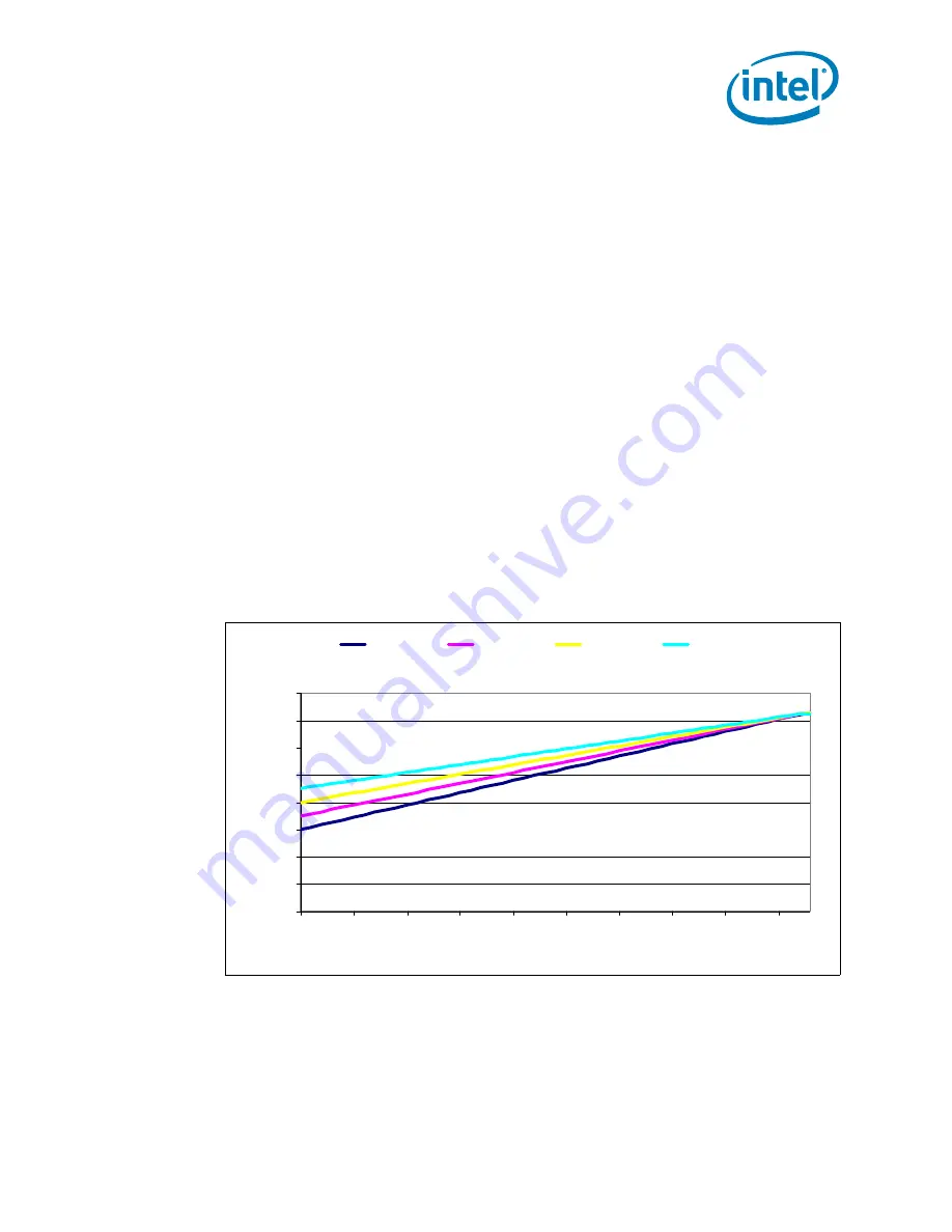
shows a number of satisfactory solutions for the Intel
®
Xeon
®
processor
3400 series (95W).
Note:
If the assumed T
AMBIENT
is inappropriate for the intended system environment, the
thermal solution performance may not be sufficient to meet the product requirements.
The results may be excessive noise from fans having to operate at a speed higher than
intended. In the worst case this can lead to performance loss with excessive activation
of the Thermal Control Circuit (TCC).
Note:
If an ambient of greater than 45.1 °C is necessary based on the boundary conditions a
thermal solution with a
Ψ
CA
lower than 0.29 °C/W will be required.
Figure 7-3. Required
Ψ
CA
for Various T
AMBIENT
Conditions
0.0
10.0
20.0
30.0
40.0
50.0
60.0
70.0
80.0
0
20
40
60
80
TTV Power Dissipation (W)
T
T
V
T
c
ase (
°C
)
Ψ
-ca = 0.45
Ta = 30 °C
Ψ
-ca = 0.40
Ta = 35 °C
Ψ
-ca = 0.34
Ta = 40 °C
Ψ
-ca = 0.29
Ta = 45.1 °C
Содержание BX80605X3440 - Quad Core Xeon X3440
Страница 10: ...Introduction 12 Thermal Mechanical Specifications and Design Guidelines...
Страница 26: ...LGA1156 Socket 28 Thermal Mechanical Specifications and Design Guidelines...
Страница 78: ...Component Suppliers 78...
Страница 80: ...Mechanical Drawings 80 Figure B 1 Socket Heatsink ILM Keepout Zone Primary Side for 1U Top...
Страница 81: ...81 Mechanical Drawings Figure B 2 Socket Heatsink ILM Keepout Zone Secondary Side for 1U Bottom...
Страница 87: ...87 Mechanical Drawings Figure B 8 Heatsink Compression Spring...
Страница 88: ...Mechanical Drawings 88 Figure B 9 Heatsink Load Cup...
Страница 89: ...89 Mechanical Drawings Figure B 10 Heatsink Retaining Ring...
Страница 91: ...91 Mechanical Drawings Figure B 12 Heatsink Backplate...
Страница 92: ...Mechanical Drawings 92 Figure B 13 Heatsink Backplate Insulator...
Страница 102: ...Socket Mechanical Drawings 104 Thermal Mechanical Specifications and Design Guidelines...
Страница 106: ...Package Mechanical Drawings 108 Thermal Mechanical Specifications and Design Guidelines...


