


5
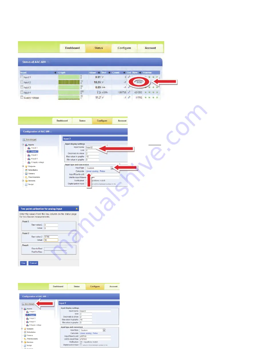
4. Now click on ‘Save changes’ and go back to the
eze
‘Status’ tab.
3. Now click on ‘Linear analog’ and enter the values as shown next:
Point 1 and Point 2 are what we want this input to read, which in this example is
‘0~10Vdc’.
Point 1 is the zero point, which is 0 for the Raw Value and 0 for the Value.
Point 2 = 9798 which is the Raw Value from step 1 at 10Vdc input, and the ‘Value’
for this example we want to read 10.
If you wish this to actually read another value, for example 100% then enter 100.
Click on ‘Use’.
2. Now go to the
eze
Configure page and click on ‘Input type’ and select ‘Custom’ as shown.
Note: Do not use the percentage symbol in the
‘Input name’ and ‘Unit’ text boxes, as this will result in
an error.
Easy steps for Calibration.
1. As an example: on the
ezeio
Controller Input 2, the analogue input is set to 0~10Vdc. Apply an accurate 10Vdc
signal to this input and on the
eze
‘Status Page’, note the ‘Raw’ reading on channel 2.
In this example below the Raw reading = 9798.


