


9
Component Identification
No.
Module name
Description
1
Hard disk fault alarming
indicator
Steady red: Hard disk in fault
Steady blue: Hard disk positioning
Steady pink: Working with RAID Rebuilding
2
Hard disk activity status
indicator
Steady green: Normal
Flashing green: Hard disk in reading/writing
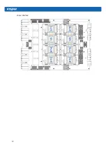
3.4 Rear panel components
No.
Module name
1-4
PSU0-3
5
FAN 0-11
6
I/O box A
7
External PCIe connector A0-A3
8
PCIE interface 4
9
PCIE interface 0
10-11
PSU4-5
12
I/O box C
13
External PCIe connector C0-C3
14-15
PCIE interface 2-3
16
BMC serial interface
17
UID button and indicator
Содержание AGX-5
Страница 1: ...Inspur Server User Manual NF5888M5 AGX 5 V1 1 ...
Страница 18: ...12 shown below ...
Страница 22: ...16 ...
Страница 37: ...31 Cabling Note Please route the cables according to the purchased machine configuration ...
Страница 46: ...40 Fig 2 11 Fig 2 12 Fig 2 13 ...
Страница 113: ...BMC settings 107 ...
Страница 116: ...110 ...
Страница 118: ...112 One key collect log One key collect log ...
Страница 123: ...BMC settings 117 ...
Страница 139: ...BMC settings 133 ...
Страница 142: ...136 ...
Страница 144: ...138 ...
Страница 149: ...BMC settings 143 ...


