


‑21‑
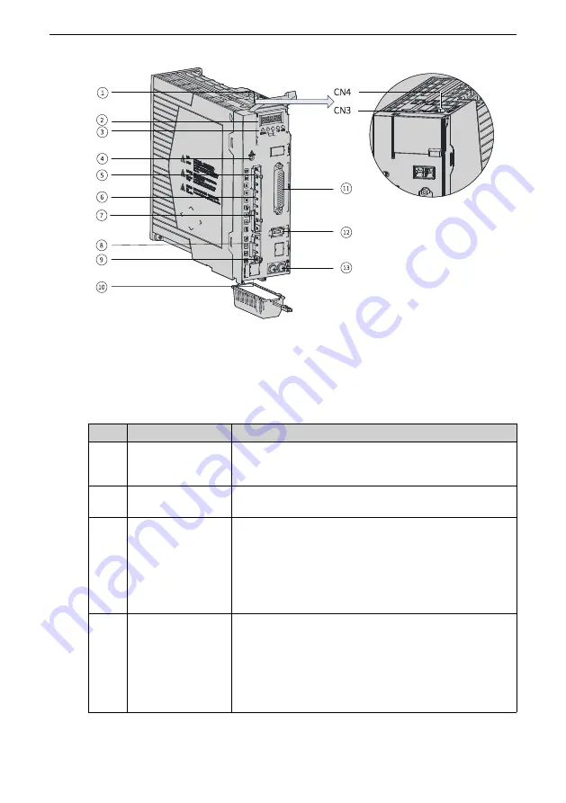
Figure 1‑10 Components of servo drives in size C and size D (size C: SV660PT3R5I and
SV660PT5R4I; size D: SV660PT8R4I and SV660PT012I)
Table 1–4 Description of components (Size C: SV660PT3R5I and SV660PT5R4I; size D:
SV660PT8R4I and SV660PT012I)
No.
Name
Description
1
CN3, CN4
(communication
terminals)
Connected to RS232 and RS485 communication command
devices in parallel.
2
5‑digit LED display
Used to display the servo drive operating status and set
parameters.
3
Keys
MODE: Used to switch parameters in sequence.
△: Used to increase the value of the blinking bit.
▽: Used to decrease the value of the blinking bit.
◁: Used to shift the blinking bit leftwards.
(Hold down: Turning to the next page when the displayed
number exceeds five digits)
SET: Used to save modifications and enter the next menu.
4
CHARGE (bus
voltage indicator)
Used to indicate the electric charge is present in the bus
capacitor. When this indicator lights up, it indicates the
electric charge may be still present in the internal
capacitor of the servo drive even though the main circuit
power supply is switched off.
To prevent electric shock, do not touch the power supply
terminals when this indicator lights up.
Содержание SV660P Series
Страница 1: ...SV660P Series Servo Drive Hardware Guide Data code 19011391 A00...
Страница 55: ...Installation 54 Figure 2 21 Installing the ferrite clamp...
Страница 66: ...Wiring 65 3 3 2 Wiring Diagram for Torque Control Mode Figure 3 5 Wiring in the torque control mode...
Страница 111: ...Wiring 110 Open collector mode For use of the internal 24 V power supply of the servo drive...
Страница 113: ...Wiring 112 Scheme 2 Using the external resistor...
Страница 135: ...Wiring 134 Selecting the regenerative resistor Figure 3 48 Flowchart for selecting the regenerative resistor...
Страница 144: ...Maintenance 143...


