27
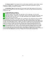
1.7 Remote Control
The compressor will not automatically restart after a power failure unless a
PORO kit is installed. The compressor can be restarted using the Green start button only if the
compressor is getting a remote run command.
1,8 Auto Stop Timer
The auto stop timer has a range of 30 to 360
seconds. Zero (0) can be
selected, which will prevent the motor from stopping. The machine will only load/unload without ever
stopping the motor.
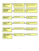
1.9 Eiger Maintenance Intervals
STD
Multiple level maintenance intervals
STD
150 Hours Runtime -150 Hrs after the initial start-up of the compressor, one time timer.
STD
2000 Hours Runtime - 2000 hours of compressor runtime since the last maintenance timer reset.
STD
8760 Hours Real Time Clock Time - (1Yr) after initial startup of the compressor or after the
maintenance timers have been reset.
STD
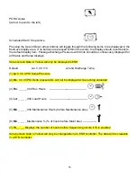
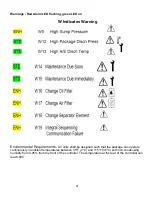
Maintenance Indicator - How to display time to maintenance; the maintenance timer will display
the maintenance timer value in hours and in percentage, (2000 or 8760) closest to reaching its
respective predetermined maintenance interval time. Once the maintenance timer value reaches 10%
(or 90%) of the preprogrammed time, (1800 hrs of runtime or 7884 hours clock time) the Wrench Icon
will flash. Once the maintenance timer value reaches 0% (or 100%) of the preprogrammed time,
(2000 hrs of runtime or 8760 hours clock time) the Red LED will flash (Warning) and wrench icon
should be on continuously and remain on until maintenance is performed and the timers are reset.
STD
Reset Maintenance Timer - Once service has been performed the Maintenance Timer values
can be reset by entering the Factory Setup Menu and scrolling to the Maintenance Timer Reset
screen and performing the reset. If for any reason a time other than 2000 hours needs to be entered it
can be done in the Maintenance rest menu. Simply set the hours wanted and press enter.
Содержание R110IU-10
Страница 5: ...5 S3 Intellisys Controller Operating Instructions...
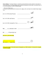
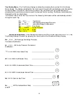
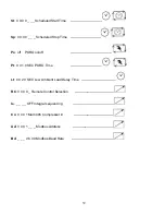
Страница 6: ...6 Software Navigation...
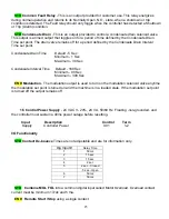
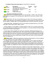
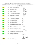
Страница 7: ...7 Eiger Controller Fault Indicators 020 Tr Motor PTC Open High Motor Temperature...
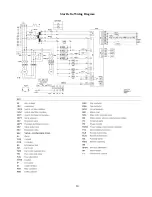
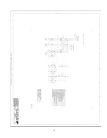
Страница 14: ...14 Star Delta Wiring Diagram...
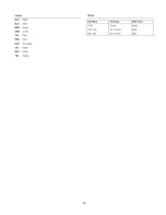
Страница 15: ...15...
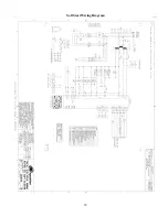
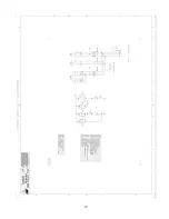
Страница 16: ...16 Soft Start Wiring Diagram...
Страница 17: ...17...
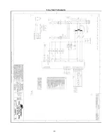
Страница 18: ...18 Line Start Schematic...
Страница 19: ...19...
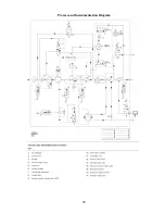
Страница 20: ...20 Process and Instrumentation Diagram...
Страница 21: ...21...
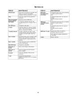
Страница 28: ...28 Maintenance...
Страница 29: ...29 Maintenance...
Страница 30: ...30 Maintenance...
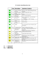
Страница 31: ...31 S3 Controller Input Output Overview AI Analog Input DI Digital Input DO Digital Output...
Страница 45: ...45 Standard S3 Menu Structure and Parameters Table 12...
Страница 46: ...46 Standard S3 Menu Structure and Parameters Table 12...
Страница 47: ...47 Standard S3 Menu Structure and Parameters Table 12...
Страница 49: ...49 Modbus Register Listing...
Страница 50: ...50 Table 13 Modbus Register Listing...
Страница 52: ...52 Appendix 1 Thermistor 2ATT 34 to 124 C 255 F Air end Discharge...
Страница 53: ...53...
Страница 54: ...54...
Страница 55: ...55...
Страница 56: ...56...
Страница 57: ...57...
Страница 58: ...58 General Specifications for Eiger Packages...
Страница 59: ...59...
Страница 60: ...60...
Страница 61: ...61...
Страница 62: ...62...
Страница 63: ...63...
Страница 64: ...64...
Страница 65: ...65...
Страница 66: ...66...
Страница 67: ...67...
Страница 68: ...68...
Страница 69: ...69...
Страница 70: ...70...
Страница 71: ...71...
Страница 72: ...72...
Страница 73: ...73...
Страница 74: ...74...
Страница 75: ...75...
Страница 76: ...76...
Страница 77: ...77...
Страница 78: ...78...
Страница 79: ...79...

