25
STD
Common Fault Relay
- This is an output provided for customer use. This relay energizes
during normal operation and returns to its Normally Open, N.O., state, when a shutdown or trip
condition is detected. The Fault relay should only toggle when the controller has detected a Shutdown
or Trip (Alarm) condition.
STD
Condensate Drain
- This is an output provided to control a condensate drain solenoid valve.
This output is a timed output that toggles on for a period of time defined by the Condensate Drain
Time set point. The drain valve remains off for a period defined by the Condensate Drain Interval
Time set point.
Condensate Drain Time Default - 5 Sec
Minimum - 1 Sec
Maximum - 30 Sec.
Condensate Interval Time Default - 180 Sec
Minimum - 90 Sec
Maximum - 300 Sec
ENH
Modulation
- The modulation output is used to turn on the modulation solenoid valve anytime
the modulation set point is turned on and the machine is in a loaded state. If the modulation set point
is turned off the output remains off.
1.5
Control Power Supply
- 24 VAC +/- 20%, 24 VA, 50/60 Hz, Floating -non-grounded, and
the controller must sustain a 40ms power outage before resetting.
Input
Description
Control
Term
Supply Controller Power X01 1-2
I/O Functionality
STD
Contact De-bounce
Times are not adjustable and are for information only. .
Dig Input #
Delay Time
1 50
ms
2 15
sec
3 15
sec
4 2
sec
5
2 sec - Closed
.5 sec - Open
6 50
ms
7 50
ms
STD
Combine MOL FOL
into a common digital input called Motor Overload. Overload contact
current must be minimum 17vdc and 5 ma.
ENH
Remote Start / Stop
using a single contact
.
Содержание R110IU-10
Страница 5: ...5 S3 Intellisys Controller Operating Instructions...
Страница 6: ...6 Software Navigation...
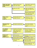
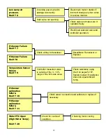
Страница 7: ...7 Eiger Controller Fault Indicators 020 Tr Motor PTC Open High Motor Temperature...
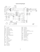
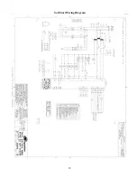
Страница 14: ...14 Star Delta Wiring Diagram...
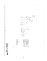
Страница 15: ...15...
Страница 16: ...16 Soft Start Wiring Diagram...
Страница 17: ...17...
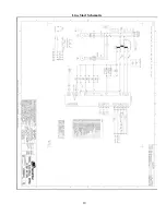
Страница 18: ...18 Line Start Schematic...
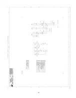
Страница 19: ...19...
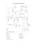
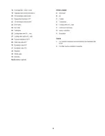
Страница 20: ...20 Process and Instrumentation Diagram...
Страница 21: ...21...
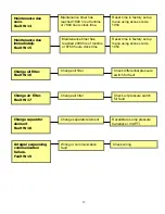
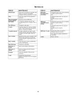
Страница 28: ...28 Maintenance...
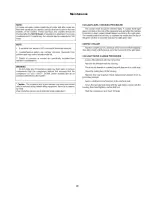
Страница 29: ...29 Maintenance...
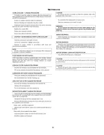
Страница 30: ...30 Maintenance...
Страница 31: ...31 S3 Controller Input Output Overview AI Analog Input DI Digital Input DO Digital Output...
Страница 45: ...45 Standard S3 Menu Structure and Parameters Table 12...
Страница 46: ...46 Standard S3 Menu Structure and Parameters Table 12...
Страница 47: ...47 Standard S3 Menu Structure and Parameters Table 12...
Страница 49: ...49 Modbus Register Listing...
Страница 50: ...50 Table 13 Modbus Register Listing...
Страница 52: ...52 Appendix 1 Thermistor 2ATT 34 to 124 C 255 F Air end Discharge...
Страница 53: ...53...
Страница 54: ...54...
Страница 55: ...55...
Страница 56: ...56...
Страница 57: ...57...
Страница 58: ...58 General Specifications for Eiger Packages...
Страница 59: ...59...
Страница 60: ...60...
Страница 61: ...61...
Страница 62: ...62...
Страница 63: ...63...
Страница 64: ...64...
Страница 65: ...65...
Страница 66: ...66...
Страница 67: ...67...
Страница 68: ...68...
Страница 69: ...69...
Страница 70: ...70...
Страница 71: ...71...
Страница 72: ...72...
Страница 73: ...73...
Страница 74: ...74...
Страница 75: ...75...
Страница 76: ...76...
Страница 77: ...77...
Страница 78: ...78...
Страница 79: ...79...

