User Manual V1.3 | XtracontrolDC2, XtracontrolET2, XtracontrolEC21
13 Appendix
13.1 Table of figures
Fig. 1: Overview XtracontrolDC2.04 (rear view)...............................................................................................................12
Fig. 2: Overview XtracontrolDC2.07 (rear view)...............................................................................................................13
Fig. 3: Overview XtracontrolET2.04 (rear view)................................................................................................................14
Fig. 4: Overview XtracontrolET2.07 (rear view)................................................................................................................15
Fig. 5: Overview XtracontrolEC21.....................................................................................................................................16
Fig. 6: Dimensions, XtracontrolDC2.04 and XtracontrolET2.04.......................................................................................20
Fig. 7: Installation cut-out, XtracontrolDC2.04 and XtracontrolET2.04............................................................................21
Fig. 8: Dimensions, XtracontrolDC2.07 and XtracontrolET2.07.......................................................................................22
Fig. 9: Installation cut-out, XtracontrolDC2.07 and XtracontrolET2.07............................................................................23
Fig. 10: Open the twist-lock catches.................................................................................................................................24
Fig. 11: Installation in an installation cut-out, example with 4 securing clips.................................................................24
Fig. 12: Device clicked home in the installation cut-out, example with 4 securing clips................................................25
Fig. 13: Installing the device.............................................................................................................................................. 26
Fig. 14: Power supply to the XtracontrolDC2 and XtracontrolEC21 plug X1 with power LED.......................................28
Fig. 15: Power supply XtracontrolET2 plug X1.................................................................................................................29
Fig. 16: Block circuit diagram, XtracontrolDC2.................................................................................................................30
Fig. 17: Block circuit diagram, XtracontrolEC21...............................................................................................................31
Fig. 18: Block circuit diagram, XtracontrolET2.................................................................................................................32
Fig. 19: Digital inputs and outputs, XtracontrolDC2 and XtracontrolEC21 plug X1 with LEDs 1 to 8............................33
Fig. 20: Circuit diagram of the principles of positive switching output...........................................................................35
Fig. 21: Circuit diagram of the principles of positive switching input..............................................................................36
Fig. 22: Operating ranges of the digital inputs (type 1/3).................................................................................................36
Fig. 23: Ethernet interface X4............................................................................................................................................ 37
Fig. 24: EtherCAT interface X5.......................................................................................................................................... 38
Fig. 25: USB interface X3................................................................................................................................................... 39
Fig. 26: RS-232 / RS-485 interface X6...............................................................................................................................41
Fig. 27: RS-485 switchable terminating resistor...............................................................................................................41
Fig. 28: CAN interface X7................................................................................................................................................... 43
Fig. 29: Analogue inputs X2.............................................................................................................................................. 44
Fig. 30: example connection: voltage input.....................................................................................................................48
Fig. 31: example connection: temperature measurement...............................................................................................49
Fig. 32: login window......................................................................................................................................................... 51
Fig. 33: list of web interface settings.................................................................................................................................52
Fig. 34: “Network Configuration” page.............................................................................................................................52
Fig. 35: Startup page with network settings.....................................................................................................................53
Fig. 36: Info page............................................................................................................................................................... 53
Fig. 37: Network settings of the device.............................................................................................................................54
Fig. 38: Netzwerkeinstellungen des Geräts.......................................................................................................................54
Fig. 39: Lifeguard-Einstellung ändern...............................................................................................................................54
Fig. 40: Summary of the network settings........................................................................................................................55
Fig. 41: identification plate with device serial number 00001 (example)........................................................................56
Fig. 42: login window......................................................................................................................................................... 56
Fig. 43: list of web interface settings.................................................................................................................................57
Fig. 44: “Network Configuration” page.............................................................................................................................57
Fig. 45: Location of the operating status LEDs.................................................................................................................58
Fig. 46: function key (S1)................................................................................................................................................... 59
Fig. 47: Undo the securing clips........................................................................................................................................66
Fig. 48: Pushing the device out of the installation cut-out...............................................................................................67
Fig. 49: Uninstalling the device......................................................................................................................................... 68
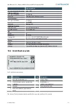
Fig. 50: Identification plate (example)...............................................................................................................................75
© Infranor GmbH
85
Содержание Xtracontrol DC2
Страница 1: ......

