28
29
Torque trend measurement
The torque trend measurement is used to deduce the change in
viscosity of the reaction medium.
The devices are
not
designed to measure absolute viscosity. They
only measure and display the relative change in the viscosity of the
medium from a starting point specified by the user.
Once the speed of the motor and magnetic rod in the medium
have stabilised to the target speed, the viscosity measurement is
started at 100%.
Consequently, an increase in the measured torque trend is indicated
by a value > 100% and a reduction in values < 100%.
The value can always be reset to 100% by pressing the “Back” (F)
membrane key.
Note:
Torque trend measurement only works for a constant set
speed for the duration of the measurement.
As a result, intermittent mode cannot be used in
conjunction with torque trend measurement.
Stirring bar decoupling
If the device detects that a stirring bar has broken away, the stirring
function is interrupted temporarily in order to pick up the bar. The
system then returns to the previously set speed. When the system
detects a bar decoupling, this is indicated with a special symbol
(
instead of symbol 16). If another stirring bar decoupling
occurs within the next 3 minutes (as long as the target speed has
not been modified), once the bar is recovered the system only goes
up to a speed of 100 rpm. In the case of 4 consecutive stirring
bar decouplings -with less than 3 minutes’ normal speed between
them - the error message ER 41 is displayed. The speed is reduced
to 200 rpm and the heating is switched off.
In such cases, the testing conditions will need to be reconsidered.
Stirring
Menu (details)
Safety
Time Out Set …………………..…………………………................ 00:30 [mm:ss]
Speed …………………………..…………………............. 100 rpm
Temperature…………………..…………………............... -
Safe temp confirmation ……..……………………………………..………… -
Er5............……..…………………………………………………………......… 05:00
Password ……..………………………………………………………………… 000
Settings
Languages
Unit Temperature
Display
Sound
Factory Settings
Communication
Information
Stirring……………………………………….... -
Heating ………………………….............…… -
Safety ……………………..…………......…… -
Software ………………………..….…..…….. -
Firmware Update Information.……………... -
Key Tone ………………………………..…….. -
Background
Firmware Update Information
ºC………………..……….…….. ºC
ºF (not available for Japan)….. -
English…………………………………………. English
Deutsch……………………………………..… -
Français………………………………………… -
Español………………………………………… -
Italiano………………………………………… -
日本語
………………………………………… -
한국어
……………………………………….... -
中文
…………………………………....………
-
Portuguese…………………………………… -
русский язык..………………………………… -
···
Bluetooth…………………..……………..…... -
-
Black ………...…….... Black
White …………………..-
Change the menu items by turning the rotary knob (D) and confirm by pushing it.
The current control variable is saved as the reference 100% ΔP
and shown on the digital display. The change in the viscosity is
then shown in %. Depending on whether the viscosity increases
or decreases, the percentage rises or falls above or below 100%
respectively.
Eurostar Control
RS 232……..…............. -
USB……..…................. -
Minimum Speed.......... -
Intermittent mode
Intermittent mode consists of regular, cyclical interruption of
the stirring function. The run time and interval can both be set.
When switching on the device, the time for each is displayed if
intermittent mode is activated.
Speed limit
The ”Speed limit” menu allows the user to set the desired maximum
upper speed limit for the stirrer. The initial setting is the maximum
permissible speed of the stirrer. If the user changes this setting, the
Wi
reless
Co
ntroller saves the new value for future stirring tasks.
If the “Speed limit” has been changed, then the speed can be ad-
justed only within the new range.
Note:
The user is responsible for ensuring the suitability/function
of the stirring bar decoupling monitoring for the current
conditions: stirring bar, speed, vessel, medium, etc.
Stirring bar decoupling monitoring does not work if the stirring
bar already breaks away before the system has reached the
set target speed!
The higher the torque to be transferred, the more safely the stirring
bar decoupling monitoring works.
In a glass beaker with water, the stirring bar decoupling for a bar
from 40 mm (d=8 mm) upwards can be seen from 300 - 1200 rpm.
Longer stirring bars, larger bar surface areas, e.g. Trika, or higher
speeds increase the torque to be transferred.
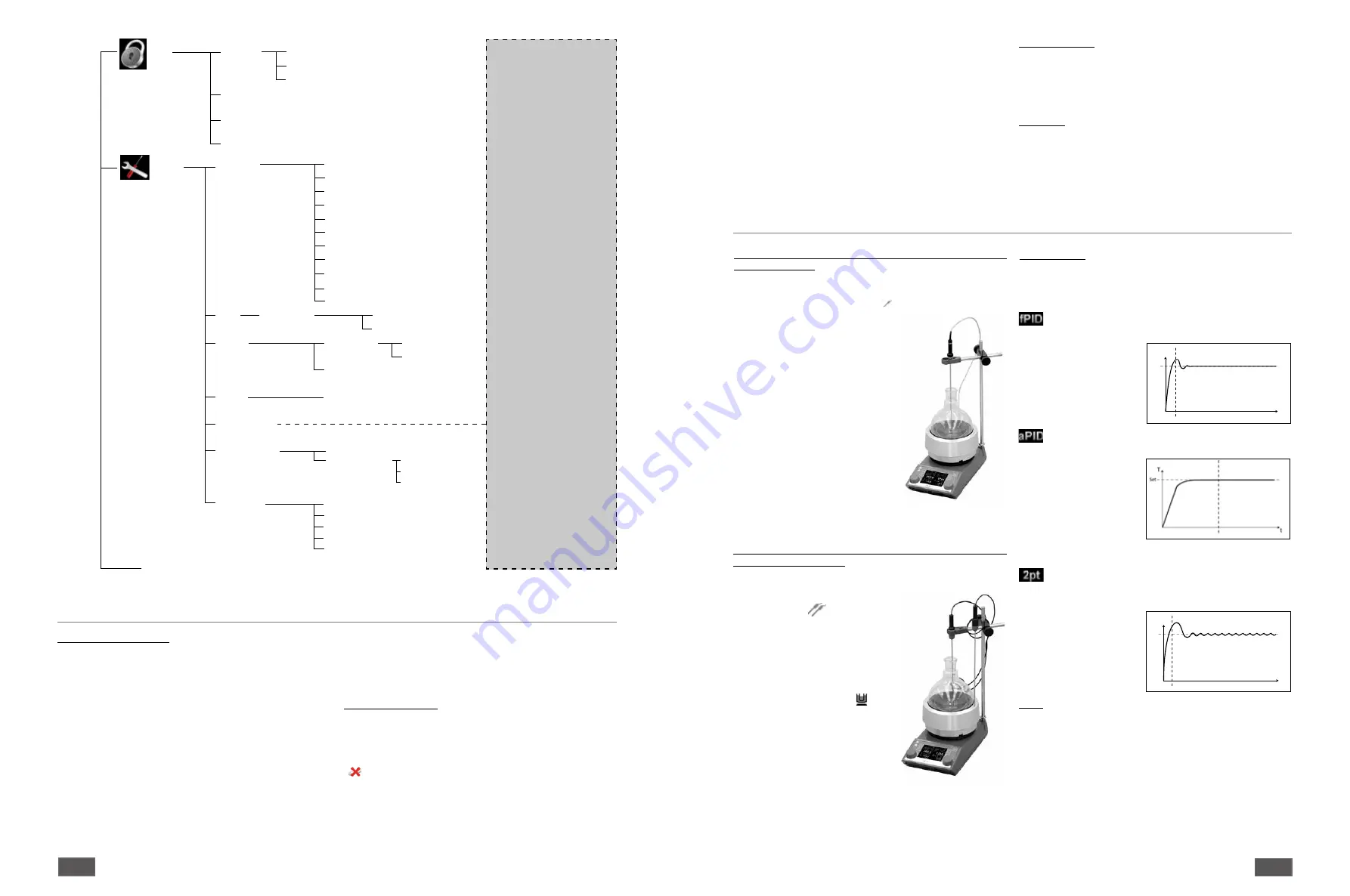
Heating
The user is able to set the device to three different methods
depending on their specific needs. The selected temperature
control method is displayed alongside the symbol (
11
).
Control method
Accurate PID:
For use with very sensitive materials which need to
be handled
carefully.
Advantages:
• very accurate warming
of the liquid
• no exceeding the target
temperature
Disadvantages:
• slow heating operating
Fast PID:
combines the advantages of the PID and two-point
methods (very fast
heating and high
accuracy; possible
overheating).
Two-point:
For media which is not too sensitive.
Advantages:
• Heating much more
rapid than
PID
Disadvantages:
• Possible overheating of
up to 10 K
T
Set
t
T
Set
t
Limits
In order to ensure that neither the medium nor the carrier fluid
overheat, the user can set separate temperature limits.
Medium limit:
The ”Medium limit” menu allows the user to set the desired
maximum temperature limit for the medium.
Carrier limit:
The ”Carrier limit” menu allows the user to set the desired
maximum temperature limit for the carrier fluid.
Limit information:
The ”Limit information” menu shows the set medium limit and
carrier limit.
Operation with the PT 1000 double
sensor is indicated on the digital
display by the
symbol. One
temperature sensor is located in the
heat carrier and the other is located
in the reaction medium. The Set
temperature value (
2
) refers to the
temperature of the medium. The
heat carrier temperature is shown on
the display as an additional current
temperature with the symbol .
The actual temperature of the reaction
medium is shown as the actual
temperature (
5
). The heating plate
temperature (and therefore the heat
carrier temperature) are limited by the
actual safety circuit temperature (
7
).
The reaction medium temperature is
limited by the set temperature limits (carrier/reaction temperature
limit).
Regulation of the temperature of the medium using PT 1000
double temperature sensor
When using the PT 100, the selected temperature control mode is
shown on the digital display by the
symbol.
The Set temperature value (
2
) and
the actual temperature (
5
) shown on
the display refer to the temperature
of the medium. The heating plate
temperature is limited by the actual
safety circuit temperature (
7
). The
medium temperature is controlled
by means of a microcontroller. The
medium temperature is measured by
the PT 100 temperature sensor and
is heated up as quickly as possible
without overshooting to the set
temperature. The microcontroller is
capable of adjusting automatically
to the different heating capacities of
various vessels and their contents. As
a result, the heat is distributed in an
optimum fashion with no temperature
drift or ripples.
Regulation of the temperature of the medium using PT 100
temperature sensor


