background image


ClearMark™ 

Installation, Operation & User Manual 

 Page 78


V 1.S.10  January 2021 


V-1.S.1 


How to import images  

The printer has some preloaded pictures and it is possible to load additional pictures & logos. 

New images must be: 


Supported formats: JPEG/JPG, PNG, ICO or BMP. 


Maximum size = 1.5 MB. 

 
If the original image is in color or grayscale, it will automatically convert it to monochromatic. 

To load a new image, follow the steps: 

1.


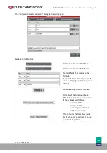
Insert a USB drive into a 

computer and create a root folder named “images”.


 [USB ROOT]: \images 

2.


Copy desired images into the new folder.  See above notes regarding formats supported. 

3.


Insert the USB drive into the TIJ printer. (USB-A connector). 

4.


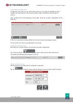
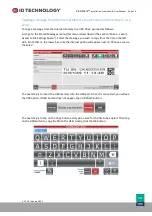
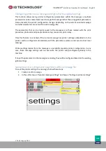
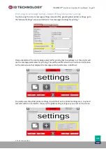
Open the message editor on the HMI.  Then: 

a.


Select an image object in the message or create one 

b.


On the Image Properties, press Image > Change Image button 

c.


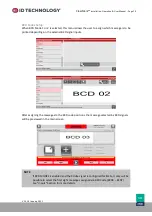
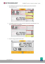
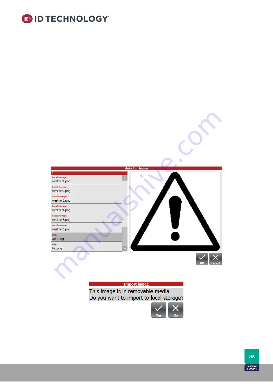
Once the list of images available appears, the new images on the USB drive will 
follow  the  existing  images  already  stored  on  the  internal  drive.  [USB  ROOT]: 
\images (Indicated as USB).  


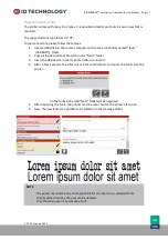
5.


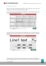
Press OK after selecting the desired image  

6.


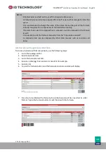
You’ll be prompted 

to confirm import of the image from the USB to the local storage: 


7.


Repeat this operation for all the images that need to be imported. 

8.


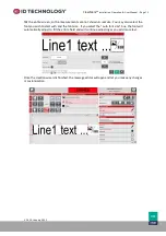
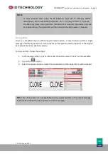
Remove the USB drive and all the imported images will now be available from the local 
storage memory of the TIJ printer. 

Содержание ClearMark

Страница 1: ...Installation Operation User Manual ID Technology ClearMark...

Страница 2: ...2021 ID Technology 5051 N Sylvania Ave Suite 405 Fort Worth TX 76137 1 888 438 3242 1 817 626 7779 www idtechnology com www promachinc com 2012 2013 2014 2015 2016 ID Technology LLC Date JANUARY 2021...

Страница 3: ...r 12 Technical specifications 12 Power Supply Source de courant Ref IDTIJ PWRSUP 13 Ink cartridge printer head 14 Printhead Temperature 15 Connectors 16 LED Indicators and Buttons 17 Internal Photocel...

Страница 4: ...5 Level 2 Print Settings 47 Print setup 47 Print Trigger and Delay Setup 49 Single print 49 Multiprint 50 Cartridge Setup 53 Stored messages File Manager Ink Cost Calculator 55 Ink Cost Calculator 57...

Страница 5: ...ading Printer Firmware 97 Appendix 4 Ink cartridge supplies 98 Appendix 5 Connectors Pinouts Connections 99 GPIO D SUB15 HD Female pin 99 External Photocell Ref IDTIJ CELL00 100 External Encoder Ref I...

Страница 6: ...uipment operators with all the necessary information to install operate and perform basic maintenance on the printer to ensure it functions properly Before using the printer it is important to follow...

Страница 7: ...Attention Presence of electrical voltage Disconnect the voltage supply to equipment work with power disconnected Pr sence de tension lectrique D branchez l quipement travaillez sans tension Explosion...

Страница 8: ...than those described in this manual will be considered unintended or improper use of the printer something which could lead to undesirable and dangerous situations Any handling of the inside componen...

Страница 9: ...SI NFPA 70 Canadian Electrical Code CEC All other applicable local and state codes Le c blage de l installation doit respecter les codes suivants Code national de l lectricit ANSI NFPA 70 Code canadie...

Страница 10: ...art 1 General Requirements European Directives EMC Directive 2014 30 EU Low Voltage Directive 2014 35 EU RoHS2 Directive 2011 65 EU EMC UNE EN 61000 6 4 2007 ERRATUM 2008 A1 2011 EMC UNE EN 61000 6 2...

Страница 11: ...ter head Delivery of the equipment Check the printer is delivered with the following items Printer module ID Technology ClearMark Power Supply See page 12 for more detail Electric power cable dependin...

Страница 12: ...VDC Electrical consumption Max 1 25 Amp Power consumption Max 30 W Consumption in stand by Without user interface 2 W With user interface 15 W USER INTERFACE Optional external screen 10 touchscreen CO...

Страница 13: ...W o Voltage Tension 24 VDC o Rated Current Courant valu 1 5 Amp o P1J connector P1J connecteur NOTE If the indicated power source is not available the following can be used Meanwell OWA 60E 24 For EU...

Страница 14: ...ffers several types of ink based on substrate and application requirements NOTE Inks contain chemical components such as pigments and solvents Ink cartridges should not be opened under any circumstanc...

Страница 15: ...ausing potential printhead damage Please actively heat the printhead If the printer needs to be used at very low temperatures and enable pulse warming Pulse warming This function pulses the printhead...

Страница 16: ...DC IN HMI RJ45 Ethernet Ethernet connection for checking status and sending printing data to the printer USB A USB Drive USB Stick Pen Drive input for Loading messages Updating the system GPIO D SUB1...

Страница 17: ...SELECT Selected message indicator LED indicators LED1 Red ERROR OFF there is no active error ON Steady Power communication to the print cartridge is off ON Blinking there is an active error LED2 Gree...

Страница 18: ...2021 Internal Photocells The printer has two photocells built into the chassis that trigger the print cycle and automatically calculate the print speed See the section Print Trigger and Printer Speed...

Страница 19: ...codes MODE 1 BCD Std MODE 2 BCD Inverted INPUT 0 IN0 START when there is a trigger it puts the device in print mode BCD 0 Bit 0 of the BCD code BCD 0 Bit 0 of the BCD code INPUT 1 IN1 STOP when there...

Страница 20: ...LED1 LED1 POWER Open collector N A LED2 LED2 PRINTING Open collector N A LED3 LED3 OPTION Open collector N A OUT_NOERROR 24VDC output signal that is high when printer is active with no errors Opto GP...

Страница 21: ...over a typical installation on a production line where the product is moving Technical Service can offer support for other types of installations Positioning the Printer Print distance Mounting the pr...

Страница 22: ...affected In applications where risk of impact is eliminated or if there is a specific need to get closer to the product surface the printhead cartridge can be adjusted to extend out and be flush with...

Страница 23: ...reduced by 2mm 2 x To remove the two small plates placed between the stall and the front faceplate of the printhead follow these steps 1 Remove the printhead covers from both sides of the head To do...

Страница 24: ...he bottom of the Cartridge Stall in the printhead a Remove the flat cables b Remove the plate that supports the board 2 x Torx10 Pop the plate out with a small flat head screwdriver 3 Loosen but do no...

Страница 25: ...rs in case they need to be reinstalled for future applications 5 Once the spacers are removed reassemble the head Tighten the lower to stall screws Reinsert the bottom plate and tighten the 2 screws C...

Страница 26: ...connects power to the cartridge and the printer is in pause b Insert or remove the cartridge c Press the button again for 5 seconds to reconnect power to the print cartridge Loading the Cartridge 1 Wi...

Страница 27: ...to the lever and or cartridge If it does not want to close ensure cartridge is inserted properly and try again Removing the Cartridge 1 Gently pull blue lever backward and then down to release and li...

Страница 28: ...r instructions on connecting the printer to the power supply An easily accessible 120VAC outlet is required near the printer to connect the power supply Connect the power source to the printer s DC IN...

Страница 29: ...the printer See Connectors chapter Once connected the HMI must be configured in order to connect and communicate with the printer After switching on the printer if the HMI does not connect the user in...

Страница 30: ...navigate the software interface without a TIJ printer connected This mode is for demonstration purposes only and any messages created may not be saved REAL Mode Connects to a live TIJ printer and per...

Страница 31: ...re three different ways to determine the speed at which the product is passing in front of the printer Fixed speed Speed calculated using internal calculation between the two internal photocells Speed...

Страница 32: ...x 300v A or B 34 150h x 300v A or B 136 300h x 600v A and B Automatically setup 68 600h x 600v A and B Automatically setup 34 The maximum print speed depends on the horizontal resolution If the requi...

Страница 33: ...he ink cartridge to the print head RESTARTING THE PRINT HEAD APPLICATION Description Restart the print head application Procedure This is done by using 2 buttons Press Button 1 On Off and at the same...

Страница 34: ...button with short pulses Action 0 Exit without command 1 COMMAND_PREPARE_USB Creates the files messages fonts and images on the USB drive 2 COMMAND_SYNC Synchronizes the files within the folders messa...

Страница 35: ...that can be executed while the printer is in boot mode To access to these operations press the buttons as indicated below This must be performed as soon as LED 1 ERROR and LED 3 SEL see LED Indicator...

Страница 36: ...eneral Issues TYPE ERROR CODE ID Description DEGREE OF QUALIFICATION REQUIRED ACTION ERROR PCA NOTDETECTED No connection with PCA Equipment technician 1 Stop and restart the printer 2 If the error per...

Страница 37: ...work related Errors TYPE ERROR CODE ID Description DEGREE OF QUALIFICATION REQUIRED ACTION ERROR NetworkInvalidInterfaces Printer cannot load the network interfaces Admin Technician 1 Configure networ...

Страница 38: ...e rest of the error message and active errors to be seen and the other tab displays a historical log of error messages To reset the printer status and resume printing press the PLAY button to start up...

Страница 39: ...l imprimante If battery needs to be replaced you can purchase an equivalent CR1220 BUTTON CELL BATTERY with the following specifications S il doit tre remplac acheter un quivalent CR1220 BATTERIE CEL...

Страница 40: ...n User Manual Page 40 V 1 S 10 January 2021 Appendix 1 User interface Navigation Settings The menu path settings and selections are organized as follow Level 0 Main Page Start up Level 1 Access to the...

Страница 41: ...ClearMark Installation Operation User Manual Page 41 V 1 S 10 January 2021 Message selection Creating a New Message Message Editor...

Страница 42: ...to the settings menu This bar appears on all screens and navigation levels so that the printer status is always visible Below are descriptions of the areas and icons found on this bar Home Button Thi...

Страница 43: ...this bar are described below Current message Name of the file selected to be printed Print preview Preview of the message to be printed Note Tap on the message to edit it Open Stored Messages Button...

Страница 44: ...be empty based on the current resolution and message selected Tap on the field if you wish to select this calculation based on the Adjusted cartridge capacity parameter If it displays 0 this indicate...

Страница 45: ...s The icons found in this menu are described below Print setup Shows the print options margin delay speed print direction etc Cartridge Setup Shows the printer cartridge options I O Status Shows the s...

Страница 46: ...MI or Printer to factory defaults restore is for admin only Trigger Setup Allows you to set up the number of prints per trigger signal and the print delays Date Shift Codes Allows customization and cr...

Страница 47: ...180 degrees Resolution To adjust the print resolution Horizontal resolution drag the slider to the desired dpi The slider will increase or decrease in steps of 25 Press and hold on the slider area to...

Страница 48: ...r revolution and the wheel diameter of the encoder used Product Photocell This box lets you select the print start signal as internal photocell or an external photocell Print Direction This box lets y...

Страница 49: ...are two options Single print ant Multiprint Single print Detailed below Print first delay Prints a continuous mark during the delay period to aid with initial setup and delay configuration Uncheck fo...

Страница 50: ...nts Select how many prints will be executed per each print signal Repeat print Selects if all the printed messages are the same or they differ i e with prints set to 4 counter will print 0001 0001 000...

Страница 51: ...nfigured at 30 mm keep in mind that the printing will start 46 mm after the trigger signal Print delays in multi print For multi print also keep in mind the blank zone at the end of the message For ex...

Страница 52: ...r Shift code Code types Used to select the desired type interval of the shift or date code Selection of code interval Configures the interval and the desired value to be printed It is not necessary to...

Страница 53: ...idge if automatic Read from cartridge is not checked Pulse width s Set the pulse width if Read from cartridge is not checked Pulse warming temperature C Set the Pulse warming temperature in C if Read...

Страница 54: ...rinting On the other hand it is possible to damage the cartridge Incorrect Pulse width will affect the print quality or damage the cartridge A Pulse warming temperature higher than the stipulated maxi...

Страница 55: ...the selected memory USB or internal Preview of the selected message Selection of the memory location internal memory or a USB Device Tools to manipulate the message preview zoom in or out view in real...

Страница 56: ...ns letting you change the name of the file to be copied and choose where you want to copy it to You can choose the printer s internal memory or an external USB memory Note If there is no USB connected...

Страница 57: ...ge is selected it loads the information about the cartridge inserted in the TIJ printer Custom cartridge option permits editing all available parameters Cartridge cost insert sell price of the cartrid...

Страница 58: ...age 58 V 1 S 10 January 2021 Information related to the ink volume of the selected cartridge Results of ink cost calculation according to the cartridge price print resolution and the selected message...

Страница 59: ...anation Tap on the box to choose which counter is shown on the main screen Number of prints that the printer has completed This total counter cannot be reset The value is increased with every print Us...

Страница 60: ...active user Enable disable AutoStart when switched on Enable disable Low level ink output Enable disable the use of message s parameters settings for printing instead of global settings Access the Adv...

Страница 61: ...ess role selection See below for details Tap on this button to edit the password used to change the user role Password User access levels There are 3 types of user access levels and the passwords are...

Страница 62: ...sociated with the basic operations of the printer such as editing print setup or to edit create messages Operator cannot edit Communications parameters or Input Setup Password required 2605 Admin This...

Страница 63: ...button and it will show the following dialogue 4 Tap on to change the required password 5 Enter the new password 6 Enter the password again to validate 7 Once the passwords have been changed tap on OK...

Страница 64: ...HMI or Printer to factory default parameters HMI Network configuration This window allows configuration of the network settings of the HMI By default the HMI is set to IP 192 168 16 203 Mask 255 255...

Страница 65: ...twork configuration of the Printer s If there is no connection configured the list of active connections will appear empty The connection can be set up automatically or manually Automatic connection s...

Страница 66: ...the network settings for the TIJ printer By default the TIJ Printer is configured RJ45 connector for HOST connection Circular Connector for HMI connection IP 192 168 1 64 IP 192 168 16 210 Mask 255 2...

Страница 67: ...k Installation Operation User Manual Page 67 V 1 S 10 January 2021 Cartridge information This tab is only available for Admin user It shows information about the cartridge currently inserted into the...

Страница 68: ...ns Graph of the encoder s behaviour over 15 seconds The encoder is sensitive to vibrations that can cause false inputs and produce poor quality print Each red pulse s edge is a direction change of the...

Страница 69: ...ation will not be processed until a change of its state is detected If inverted is checked the signal will be processed when a falling edge is detected o State signal activation will be processed if t...

Страница 70: ...printed depending on the external BCD signal inputs After assigning the messages to the BCD code positions the message selected by BCD signals will be previewed in the main screen NOTE If BCD MODE2 is...

Страница 71: ...emplates available Keep in mind that these templates are for reference only and can be edited later The second step lets you quickly change the selected template You can change the number of objects i...

Страница 72: ...eal size You may also select the font you wish to start with and the font size If you select the auto font size box the font will automatically adjust to fill the entire field and will continue adjust...

Страница 73: ...e menu lets you perform basic operations save close undo changes etc and perform actions move create new objects select objects etc When you click on the Create button a wizard will open to help you c...

Страница 74: ...xt field insert a monochromatic image create a barcode static or dynamic and draw rectangles lines ellipses or diamonds When you tap on any of these buttons different submenus open depending on the ob...

Страница 75: ...Access to the Settings Menu Select the message you wish to copy from the list on the left side Note that on the lower bar only the internal option will appear next to Choose a source the Drive The ne...

Страница 76: ...o the Stored Messages menu selecting the USB device and looking for the file name in the list To copy a message from USB device to the internal memory of the printer you need to have a folder named me...

Страница 77: ...y all the desired Font files ttf in this fonts folder 3 Insert the USB device in the TIJ printer USB A connector 4 After a few seconds the HMI will ask for confirmation to import the fonts into the pr...

Страница 78: ...notes regarding formats supported 3 Insert the USB drive into the TIJ printer USB A connector 4 Open the message editor on the HMI Then a Select an image object in the message or create one b On the I...

Страница 79: ...d is a property for each 2D code To enable the feature please follow these steps 1 Go to the Message Editor and create or edit a message 2 Add edit a QR Code or Datamatrix code 3 With the 2D Barcode s...

Страница 80: ...age or edit one 4 Add or edit an item 5 Tap on Data Source and select Date Time 6 Tap on Format and select the same date time as created in step 2 They are at the end of the list between brackets or u...

Страница 81: ...nput the value which will have the User Input element i e Prompt could be enter lot number Value could be 123456 5 Save and select the message and exit the editor 6 A pop up window will appear with th...

Страница 82: ...ows to design messages with multiple items in one field that are composed of other items To create a composite item follow these steps 1 Go to the message editor 2 Add or edit an item 3 Select item to...

Страница 83: ...ld Table of fields that compose the formula It is possible to edit the type and the value by tapping on the pencil icon of each Move fields up down or remove Formula of the composed item This field is...

Страница 84: ...entry of the field VALUE as text The output of the calculated formula is the text entered o ITEM choose an Item field from the Value list that already exists in the message to include it in the formul...

Страница 85: ...Once finished the Composite item will be available to edit and it will show the formula and the result 8 It is possible to hide items in order to print them only inside the composite item To do this...

Страница 86: ...ire barcode will be converted to a GS1 format Tap to the formula button to edit the AI with the formula NOTES Only barcodes and text can be used for composite data source A Composite item cannot be co...

Страница 87: ...he Barcode assistant 9 Set any items not that are not required to be printed as not printable 10 Save the message and exit editor NOTE It is possible to change the symbology of the barcode and reassig...

Страница 88: ...same properties as the original item except the field name position and size To copy paste an item follow these steps 1 In the message editor select an item by tapping on it 2 Press on the selected i...

Страница 89: ...tton named Clone will be available 2 Tap on the button 3 Select the canvas mode to create the cloned item and the cloned item will be created NOTES To Copy Paste when using the PC Software right click...

Страница 90: ...and speed encoder setup resolution print delay Once this feature is activated if the current message has printer settings embedded in it the printer will be configured automatically with the parameter...

Страница 91: ...le local settings will appear These will be stored within the message Default values are populated from the global settings 4 Enable and configure the settings that will be saved locally in the messag...

Страница 92: ...messages settings for printing Once enabled and if current message selected for printing has the settings in it the printer will use the message parameters for printing This will be confirmed with an...

Страница 93: ...face Messages can be created but not saved REAL Operation is the same as using the 10 HMI and in this mode it is possible to save the designed messages on the PC to be transferred to a head later To c...

Страница 94: ...printer an Ethernet connection to the RJ45 port is necessary See Connectors chapter Before connecting the PC must be properly configured to connect and communicate with the printer By default the TIJ...

Страница 95: ...inters network settings and set a connection 2 Go to Stored Messages 3 Tap on button and the following screen will appear Where Left side List of message files loaded in the internal memory of the TIJ...

Страница 96: ...gs and remove any active connections Alternatively you can simply disconnect any ethernet connections Once removed or disconnected the messages will be saved to computer memory The directory where the...

Страница 97: ...6 a If all 3 LEDs are flashing at the same time it means that the TIJ update process has finished properly To reboot he system the user must press POWER button for 2 seconds and once released the syst...

Страница 98: ...dge life varies depending on Cartridge has a Shelf Life Check it carefully Changing ink Firing parameters modifies ink consumption Seechapter Settings Cartridgesetup for further details Cartridge volu...

Страница 99: ...r on the TIJ printer is a general purpose Input Output connector with the following pin assignments Pin Description 1 IN0 IN_BCD0 START 9 IN1 IN_BCD1 STOP 2 IN2 IN_BCD2 10 IN3 IN_BCD3 3 IN4 IN_STROBE...

Страница 100: ...Manual Page 100 V 1 S 10 January 2021 External Photocell Ref IDTIJ CELL00 The external photocell is powered by 24 V from the GPIO port and comes with a tube 10 mm in diameter and 500 mm in length Cut...

Страница 101: ...on Operation User Manual Page 101 V 1 S 10 January 2021 External Encoder Ref IDTIJ ENCODER00 The external encoder to be used with the printer is 24 V 5000 ppr Channel A and B Wheel 72 5 mm in diameter...

Страница 102: ...onnector for GPIO Y Cable Ref IDTIJ YCAB00 The D SUB15HD GPIO connector can be used to connect several accessories in parallel This allows for connection of an external photocell encoder and BCD input...

Страница 103: ...PLCs etc Connection Pinout SUBD15 s PIN Fly wire s colour Signal 1 Blue IN 1 BCD 0 2 Pink IN 3 BCD 2 3 Grey IN 5 BCD STROBE 4 White Yellow Vin 24 Vdc 5 Yellow GND 6 Black ENCODER 1 7 Red GND 8 Brown G...

Страница 104: ...er based on the alarm output signal OUT_NOERROR Green printer running without errors Red printer in error status Green and red blinking printer is running but warning of low ink level Connection diagr...

Страница 105: ...05 V 1 S 10 January 2021 Standard Support Ref IDTIJ BRACKET00 General purpose support bracket used to mount the printer to the production line and includes attachments for The printer The Touchscreen...

Страница 106: ...ouch Screen HMI To connect up to 4 printers the following is required 1x IDTIJ JBOX00 Junction Box 4 x Cables to interface with each printer Each cable is 3m long and connects the 15 pin I O connector...

Страница 107: ...ct to an external PC DB15HD Female to connect BCD Signals These signals are then shared between all the printers connected DB15HD Female to connect an external product photocell This signal is shared...

Страница 108: ...onnected and they are in good working order if the Junction Box does not power up 24Vdc Power supply Junction Box contains a 24Vdc power supply to supply up to 4 TIJ printers Mean well LRS 100 24 AC I...

Страница 109: ...1 Internal Connectors The following table outlines the internal connections of this board J302 is the main power connector Printer status LEDs J223 LED HEAD 1 J224 LED HEAD 2 J225 LED HEAD 3 J226 LED...

Страница 110: ...ition 1 2 JP201 Printer 1 JP202 Printer 2 JP203 Printer 3 JP204 Printer 4 Place each the jumper in position 1 2 only if it is desired to power the printer through the Junction Box and not through its...

Страница 111: ...on Box When printheads are connected to the junction box it is possible to control up to four printheads using one HMI touch screen or PC NOTE All the network devices HMI Printers connected to a junct...

Страница 112: ...ishes booting up you will be at the launch screen for the ClearMark software 2 Press the Settings button in the top right hand corner then press the General Settings button on the bottom left hand sid...

Страница 113: ...e you will EDIT the printheads IP Address for use with the Junction Box RJ45 connection 6 Change the printers RJ45 gateway address to the proper IP circled below 7 Edit the IP Address as required on t...

Страница 114: ...side of the screen Then press the center tab which is labelled Advanced Settings Press the first option under Network Settings which is HMI Network Settings and change the HMI IP address to the 192 16...

Страница 115: ...of 4 indicator icons that display the general status and name for each printer o Green the printer is ready to print o Red the printer is in error mode includes stopped o Yellow the printer is in war...

Страница 116: ...ClearMark Installation Operation User Manual Page 116 V 1 S 10 January 2021 Junction Box Electrical schematic...

Отзывы: