I-7530A-MR Modbus RTU to CAN
Converter User’s Manual (Version 1.07, 06/2016) ------------- 18
Figure 2-16
:
Normal Position of Dip-Switch
2.5.3
Module Configuration Mode
During the module is running in the Firmware Operation Mode, set the
DIP-switch to the
“Init” (Initial) position as Figure 2-12 and wait for three
seconds. The module
’s PWR LED still turns on and the others LEDs will
flash approximately once per second. That means the I-7530A-MR
module is working in the
“Module Configuration Mode”. In this mode,
users can use UART2CAN Utility to configure the communication
parameters and communication modes of the module.
2.6
LED Indication
There are three LEDs to indicate what the state of the I-7530A-MR is
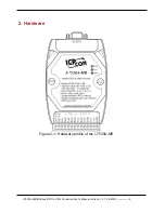
in. The positions of these three LEDs are shown as Figure 2-17.
(1) PWR LED :
It is used to help users with checking if the I-7530A-MR is standby. If
the module is supplied the proper power, the PWR LED is turned on. The
different situations of the module may cause the different blinking display.
The PWR LED is always turned on when the module works in a good
condition. When the Bus-Off error is happened, the PWR LED will blink
every 500 ms until the Bus-Off condition disappears. If the CAN message
can
’t be sent out successfully, the PWR LED will blink every 100 ms.


