5
Icotera A/S, Vibeholms Allé 16, 2605 Brøndby, Denmark - [email protected]
Document version: 1.0
User Guide for 1.17.3 Firmware
Please note that for some configurations the 5 GHz WiFi interface may be unavailable for up
to 10 minutes due to prolonged radar detection mechanism, which is signalled by the WiFi
LED blinking. If the 2.4GHz WiFi is enabled, it will operate normally.
Connectors
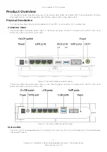
The i68xx front panel includes all the local user connectors that are four RJ-45 10Base-T/100Base-TX/1000Base-T
ports, two USB ports, two POTS phone ports and one F-type CATV RF output port. Optical fiber connectors are
placed inside the device. The rest of the fibers (reserve) is covered by a tray which is screwed down to the device
coaster. It is necessary to take the device cover off in order to access the fibers.
The i4850 bottom panel includes five RJ-45 10Base-T/100Base-TX/1000Base-T ports (1xWAN and 4xLAN), two
USB ports, and two POTS phone ports.
100Base-BX/1000Base-BX Optical Port
The i68xx uses standard SC port connectors to attach 9/125 micron single mode fiber optic cables. For data it is
an SC/PC connector with a TX wavelength of 1310 nm and an RX wavelength of 1550 nm, and for CATV it is an SC/
APC connector with a wavelength ranging from 1290 to 1600 nm.
10Base-T/100Base-TX/1000Base-T Ports
The Icotera CPEs use 10Base-T/100Base-TX/1000Base-T RJ-45 (8-pin modular) port connectors. The 10Base-
T/100Base-TX/1000Base-T port connectors are configured as MDI–X (Medium Dependent Interface – Crossover).
The CPE uses auto sense ports that are designed to operate at 10 Mb/s, 100 Mb/s, or at 1000 Mb/s, depending on
the connecting device. These ports support the IEEE 802.3u auto negotiation standard, which means that when a
port is connected to another device that also supports the IEEE 802.3u standard, then the two devices negotiate
the best speed and duplex mode. The 10Base-T/100Base-TX/1000Base-T RJ-45 switch ports also support half- and
full-duplex mode operation and can connect to 10 Mb/s, 100 Mb/s or 1000 Mb/s Ethernet segments or nodes.
USB Ports
The Icotera CPE is equipped with one USB 3.0 and one USB 2.0 port that supply 5 V at 500 mA.
POTS Ports
The Icotera CPE uses FXS RJ-11 (2-pin modular) port connectors for POTS (VoIP) connections. The CPE has two
FXS ports, so it is possible to configure two independent telephone numbers.
Power Port
The power port accepts DC 12V power source. It is important to make sure that the proper power adapter is suitable
to a particular region.
On/Off Switch
The On/Off switch enables you to switch the CPE on or off, as well as reboot it and restore the last saved configuration.
Reset Button
The Reset button has four modes of operation:
•
when CPE is operating -
pressed for less than 10 seconds:
restarts CPE - WAN LED blinks green.
•
when CPE is operating -
pressed for more than 10 seconds:
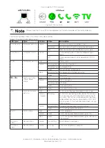
restores default CPE settings - WAN and VoIP 1
LEDs blink green.
•
when CPE is off -
power-on with reset button pressed for less than 10 seconds:
restores default CPE settings
- WAN LED blinks green.
•
when CPE is off -
power-on with reset button pressed for more than 10 seconds:
boots CPE from the second
bank - WAN and VoIP 1 LEDs blink green.
Serial Number
The serial number of the Icotera CPE consists of 13 digits. The format of the serial number is PPPPCCXXXXXXX,
where PPPP is the product ID, CC is the product variant, and XXXXXXX is the running serial number. For example
6855001234567 would be a serial number of the i6855-00 device with a running number of 1234567


