background image

v

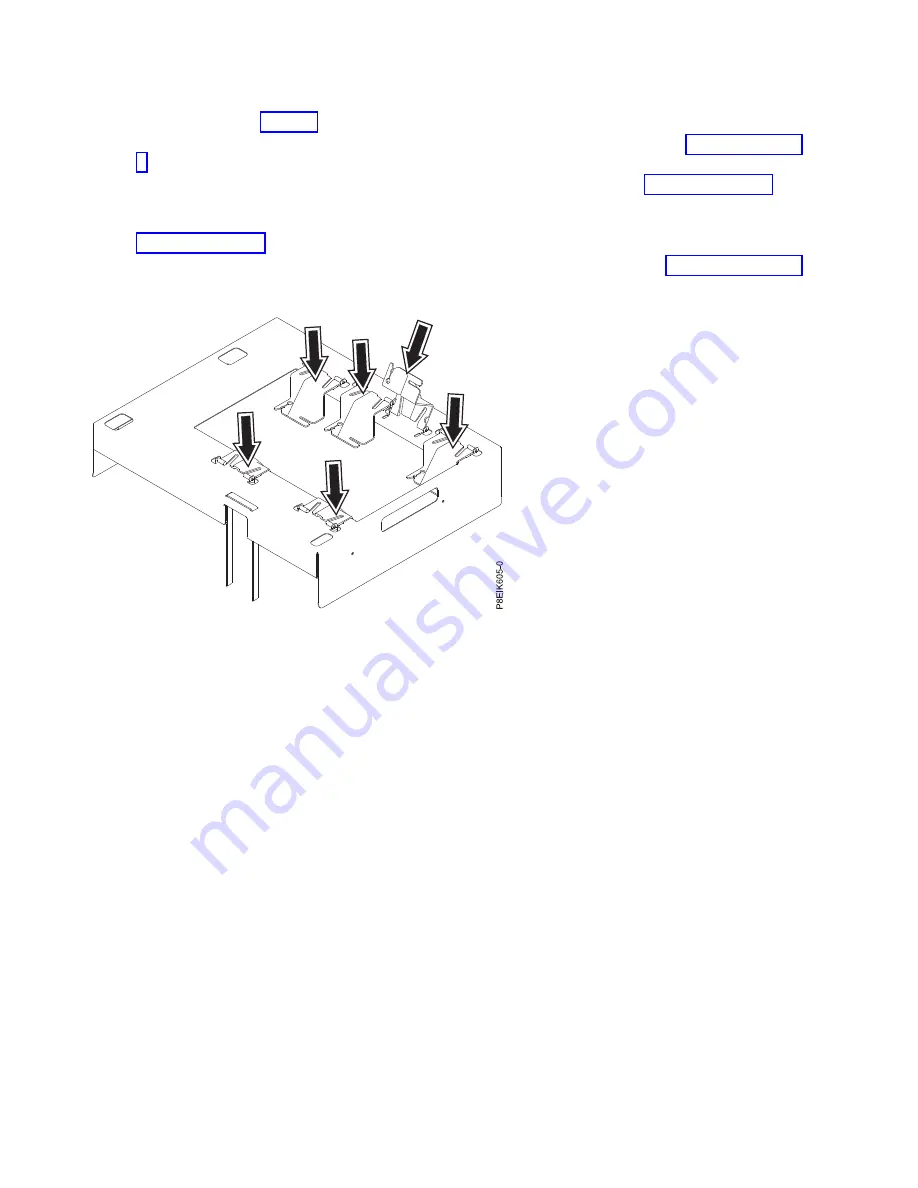
The cold plate installation carrier has a plastic holder for each cold plate, directly over each cold
plate as shown in Figure 6. The carrier has two extra holders.

v

Each plastic holder can pivot up as needed to access the cold plates as shown in Figure 7 on page
7.

v

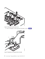
Lift and pinch the plastic holder to remove it from the carrier as shown in Figure 8 on page 7.
Removing the plastic holder makes it easier to attach and release the cold plate from the holder.

v

Each plastic holder has two slots to secure the two pins on the top of each cold plate as shown in
Figure 9 on page 8. Slide the holder near to the top of the pins, the pins are narrower at the top.

v

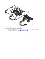
The carrier has a hook-and-loop fastener to hold the water hoses as shown in Figure 10 on page 8.

Figure 6. The cold plate installation carrier and the cold plate holders. The installation carrier is a metal frame that fits
over the chassis. A plastic holder supports each cold plate; the holders are located directly over each cold plate.

6

Power Systems: Servicing the IBM Power System S822LC (8335-GTB)

Содержание S822LC

Страница 1: ...Power Systems Servicing the IBM Power System S822LC 8335 GTB IBM ...

Страница 2: ......

Страница 3: ...Power Systems Servicing the IBM Power System S822LC 8335 GTB IBM ...

Страница 4: ... Notices manual G229 9054 and the IBM Environmental Notices and User Guide Z125 5823 This edition applies to IBM Power Systems servers that contain the POWER8 processor and to all associated models Copyright IBM Corporation 2016 2017 US Government Users Restricted Rights Use duplication or disclosure restricted by GSA ADP Schedule Contract with IBM Corp ...

Страница 5: ...ry and memory risers in the 8335 GTB 70 Removing and replacing memory DIMM in the 8335 GTB 70 Removing and replacing memory risers in the 8335 GTB 75 Removing memory risers from the 8335 GTB 75 Replacing memory risers in the 8335 GTB 77 Plugging rules for memory in the 8335 GTB system 78 Removing and replacing PCIe adapters in the 8335 GTB 79 Removing a PCIe adapter from the system backplane in th...

Страница 6: ...ting and stopping the 8335 GTB 199 Starting the 8335 GTB system 199 Stopping the 8335 GTB system 199 Event sensor status GUI display 200 Removing and replacing covers on an 8335 GTB system 202 Removing the service access cover from an 8335 GTB system 202 Installing the service access cover on an 8335 GTB system 203 Removing the front cover from an 8335 GTB system 204 Installing the front cover on ...

Страница 7: ...itional copies of safety information documentation can be obtained by calling the IBM Hotline at 1 800 300 8751 German safety information Das Produkt ist nicht für den Einsatz an Bildschirmarbeitsplätzen im Sinne 2 der Bildschirmarbeitsverordnung geeignet Laser safety information IBM servers can use I O cards or features that are fiber optic based and that utilize lasers or LEDs Laser compliance I...

Страница 8: ...nect 1 Turn off everything unless instructed otherwise 2 For AC power remove the power cords from the outlets 3 For racks with a DC power distribution panel PDP turn off the circuit breakers located in the PDP and remove the power from the Customer s DC power source 4 Remove the signal cables from the connectors 5 Remove all cables from the devices To Connect 1 Turn off everything unless instructe...

Страница 9: ...emperatures will exceed the manufacturer s recommended ambient temperature for all your rack mounted devices v Do not install a unit in a rack where the air flow is compromised Ensure that air flow is not blocked or reduced on any side front or back of a unit used for air flow through the unit v Consideration should be given to the connection of the equipment to the supply circuit so that overload...

Страница 10: ...e potential hazards v Verify that the route that you choose can support the weight of the loaded rack cabinet Refer to the documentation that comes with your rack cabinet for the weight of a loaded rack cabinet v Verify that all door openings are at least 760 x 230 mm 30 x 80 in v Ensure that all devices shelves drawers doors and cables are secure v Ensure that the four leveling pads are raised to...

Страница 11: ...DANGER Rack mounted devices are not to be used as shelves or work spaces L002 L003 1 2 or 1 2 or 1 2 3 4 or Safety notices ix ...

Страница 12: ... be equipped with multiple AC power cords or multiple DC power cables To remove all hazardous voltages disconnect all power cords and power cables L003 L007 CAUTION A hot surface nearby L007 L008 x Power Systems Servicing the IBM Power System S822LC 8335 GTB ...

Страница 13: ...ptacle Although shining light into one end and looking into the other end of a disconnected optical fiber to verify the continuity of optic fibers many not injure the eye this procedure is potentially dangerous Therefore verifying the continuity of optical fibers by shining light into one end and looking at the other end is not recommended To verify continuity of a fiber optic cable use an optical...

Страница 14: ...rhanging load v Do not use on uneven surface incline or decline major ramps v Do not stack loads v Do not operate while under the influence of drugs or alcohol v Do not support ladder against LIFT TOOL v Tipping hazard Do not push or lean against load with raised platform v Do not use as a personnel lifting platform or step No riders v Do not stand on any part of lift Not a step v Do not climb on ...

Страница 15: ...ding interfaces only Type 2 or Type 4 ports as described in GR 1089 CORE and require isolation from the exposed OSP cabling The addition of primary protectors is not sufficient protection to connect these interfaces metallically to OSP wiring Note All Ethernet cables must be shielded and grounded at both ends The ac powered system does not require the use of an external surge protection device SPD...

Страница 16: ...xiv Power Systems Servicing the IBM Power System S822LC 8335 GTB ...

Страница 17: ...rrect missing or visibly damaged contact the provider of the part or your next level of support DANGER When working on or around the system observe the following precautions Electrical voltage and current from power telephone and communication cables are hazardous To avoid a shock hazard v If IBM supplied the power cord s connect power to this unit only with the IBM provided power cord Do not use ...

Страница 18: ... cables to the connectors 4 For AC power attach the power cords to the outlets 5 For racks with a DC power distribution panel PDP restore the power from the Customer s DC power source and turn on the circuit breakers located in the PDP 6 Turn on the devices Sharp edges corners and joints may be present in and around the system Use care when handling equipment to avoid cuts scrapes and pinching D00...

Страница 19: ... your hardware v When you use an ESD wrist strap follow all electrical safety procedures An ESD wrist strap is used for static control It does not increase or decrease your risk of receiving electric shock when using or working on electrical equipment v If you do not have an ESD wrist strap just prior to removing the product from ESD packaging and installing or replacing hardware touch an unpainte...

Страница 20: ...ses through the rear wall of the system as shown in Figure 3 and Figure 4 on page 5 Figure 2 Removing the rear service clip Figure 3 Removing the hoses 4 Power Systems Servicing the IBM Power System S822LC 8335 GTB ...

Страница 21: ...plate installation carrier In this step learn about the carrier and how to use it to more easily work with the cold plate assembly Figure 4 Passing the connectors through the rear wall one at a time Figure 5 Resting the hoses on the rear wall Removing and replacing parts in the IBM Power System S822LC 8335 GTB 5 ...

Страница 22: ...e the cold plate from the holder v Each plastic holder has two slots to secure the two pins on the top of each cold plate as shown in Figure 9 on page 8 Slide the holder near to the top of the pins the pins are narrower at the top v The carrier has a hook and loop fastener to hold the water hoses as shown in Figure 10 on page 8 Figure 6 The cold plate installation carrier and the cold plate holder...

Страница 23: ...ccess the cold plate Figure 8 Removing a holder from the carrier You can pinch the plastic holder to remove it from the carrier You can more easily attach the cold plate pins to the holder when that holder is removed from the carrier Removing and replacing parts in the IBM Power System S822LC 8335 GTB 7 ...

Страница 24: ...r has two slots to secure the two pins that are on the top of each cold plate A First secure one pin to the holder then B rotate the holder to secure the second pin In C both pins are secured to the holder Figure 10 Fastening the water hoses to the carrier The carrier has a hook and loop fastener to hold the water hoses when you are moving the entire cold plate assembly and carrier 8 Power Systems...

Страница 25: ... over the system as shown in Figure 12 on page 10 Ensure that the alignment pins in the carrier fit into holes for the top cover Figure 11 Opening the hook and loop fastener Removing and replacing parts in the IBM Power System S822LC 8335 GTB 9 ...

Страница 26: ...rs secure the water hoses to the cold plate installation carrier as shown in Figure 13 on page 11 Figure 12 Lowering the cold plate installation carrier onto the system 10 Power Systems Servicing the IBM Power System S822LC 8335 GTB ...

Страница 27: ...the cold plates that have their hoses closest to the top of the system ending with the cold plates that have hoses closest to the bottom of the system a To access the screws that secure the GPU or processor cold plate rotate the holder up as shown in Figure 14 on page 12 Figure 13 Fastening the water hoses to the carrier Removing and replacing parts in the IBM Power System S822LC 8335 GTB 11 ...

Страница 28: ...e retainer open as shown in Figure 15 on page 13 Attention Do not unscrew the four spring loaded screws that attach the aluminum heat cover to the GPU Figure 14 Holder pivoted up to access cold plate 12 Power Systems Servicing the IBM Power System S822LC 8335 GTB ...

Страница 29: ...turning the supplied hex key counterclockwise as shown in Figure 16 Loosen the screw until it moves freely Figure 15 Open the cold plate retainer Figure 16 Loosening the cold plate retainer screw Removing and replacing parts in the IBM Power System S822LC 8335 GTB 13 ...

Страница 30: ...in Figure 18 Push the pin into the slot only as far as is needed c Pivot the cold plate to slide the other pin into the holder as shown in B in Figure 18 Push the pin into the slot only as far as is needed d Pinch the holder at the sides B as shown in Figure 19 on page 15 and replace it onto the carrier Figure 17 Removing holder from carrier Figure 18 Inserting the cold plate pins into the holder ...

Страница 31: ...e cold plate installation carrier lift the carrier straight up off the system as shown in Figure 20 on page 16 If you lift at an angle the carrier catches on the cold plate clips Figure 19 Replacing the holder back onto the carrier Removing and replacing parts in the IBM Power System S822LC 8335 GTB 15 ...

Страница 32: ... the cold plate installation carrier that us used for the IBM Power System S822LC 8335 GTB system Before you begin To replace a faulty cold plate or water hose you first need to do the procedure Removing the cold plates from the 8335 GTB system on page 3 Procedure 1 On your work table place the replacement cold plate assembly A next to the cold plate installation carrier as shown in Figure 21 on p...

Страница 33: ...c holder Lift and pinch the plastic holder at points A to remove it from the carrier as shown in Figure 22 on page 18 Figure 21 Placing the replacement cold plate assembly next to the cold plate installation carrier Removing and replacing parts in the IBM Power System S822LC 8335 GTB 17 ...

Страница 34: ...to slide one pin from the holder as shown in Figure 23 Figure 22 Removing the holder from the carrier Figure 23 Removing the first cold plate pin from the holder 18 Power Systems Servicing the IBM Power System S822LC 8335 GTB ...

Страница 35: ... as shown in Figure 24 d Pinch the holder at points A and replace it onto the carrier as shown in Figure 25 on page 20 Figure 24 Removing the second cold plate pin from the holder Removing and replacing parts in the IBM Power System S822LC 8335 GTB 19 ...

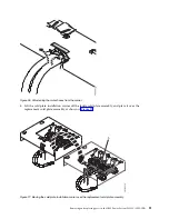
Страница 36: ... After all the cold plates are secured to their corresponding GPU or processor module unfasten the hook and loop fastener from the water hoses as shown in Figure 26 on page 21 Figure 25 Replacing the holder back onto the carrier 20 Power Systems Servicing the IBM Power System S822LC 8335 GTB ...

Страница 37: ...e it over the replacement cold plate assembly as shown in Figure 27 Figure 26 Unfastening the water hoses from the carrier Figure 27 Moving the cold plate installation carrier over the replacement cold plate assembly Removing and replacing parts in the IBM Power System S822LC 8335 GTB 21 ...

Страница 38: ... in Figure 28 6 Secure each cold plate to its corresponding plastic carrier a Pivot the holder up Pinch in at the sides to remove the holder from the carrier as shown in Figure 29 on page 23 Figure 28 Fastening the water hoses to the carrier 22 Power Systems Servicing the IBM Power System S822LC 8335 GTB ...

Страница 39: ...in into the holder as shown in B in Figure 30 Push the pin into the slot only as far as is needed d Pinch the holder at the sides B as shown in Figure 31 on page 24 and replace it onto the carrier Figure 29 Removing holder from carrier Figure 30 Inserting the cold plate pins into the holder Removing and replacing parts in the IBM Power System S822LC 8335 GTB 23 ...

Страница 40: ...ystem S822LC 8335 GTB system Before you begin Ensure that you have enough TIMs for the GPUs and processors Check the FRU kit The GPU TIM part number is 00E5133 The processor TIM part number is 45D7426 Procedure 1 Ensure that you have the electrostatic discharge ESD wrist strap attached If not attach it now 2 Ensure that each GPU clip is open as shown in Figure 32 on page 25 Figure 31 Replacing the...

Страница 41: ...page 26 If the TIM is damaged use the supplied scraper to remove the TIM from the cold plate Using the tweezers center the new TIM onto the system processor module The side with the red stripe must be facing up Align the beveled edges of the TIM and the system processor module Figure 32 Open the cold plate retainer Removing and replacing parts in the IBM Power System S822LC 8335 GTB 25 ...

Страница 42: ...traight down onto the system as shown in Figure 34 on page 27 If you lower at an angle the carrier catches on the cold plate clips Figure 33 Installing the TIM onto the processor lid 26 Power Systems Servicing the IBM Power System S822LC 8335 GTB ...

Страница 43: ...ear the front of the system a Remove a cold plate from its plastic holder Lift and pinch the plastic holder at points A to remove it from the carrier as shown in Figure 35 on page 28 Figure 34 Lowering the cold plate installation carrier onto the system Removing and replacing parts in the IBM Power System S822LC 8335 GTB 27 ...

Страница 44: ...to slide one pin from the holder as shown in Figure 36 Figure 35 Removing the holder from the carrier Figure 36 Removing the first cold plate pin from the holder 28 Power Systems Servicing the IBM Power System S822LC 8335 GTB ...

Страница 45: ... as shown in Figure 37 d Pinch the holder at points A and replace it onto the carrier as shown in Figure 38 on page 30 Figure 37 Removing the second cold plate pin from the holder Removing and replacing parts in the IBM Power System S822LC 8335 GTB 29 ...

Страница 46: ...sor module v For a GPU swing the retainer over the GPU and tighten the cold plate retainer screw as shown in Figure 39 on page 31 Figure 38 Replacing the holder back onto the carrier 30 Power Systems Servicing the IBM Power System S822LC 8335 GTB ...

Страница 47: ...ld plate retainer screw with the supplied hex key as shown in Figure 40 Figure 39 Secure the cold plate retainer screw Figure 40 Tightening the cold plate retainer screw Removing and replacing parts in the IBM Power System S822LC 8335 GTB 31 ...

Страница 48: ...processor module unfasten the hook and loop fastener from the water hoses as shown in Figure 41 7 Lift the cold plate installation carrier straight up off the system as shown in Figure 42 on page 33 Figure 41 Unfastening the water hoses from the carrier 32 Power Systems Servicing the IBM Power System S822LC 8335 GTB ...

Страница 49: ...tem as shown in Figure 43 and Figure 44 on page 34 Figure 42 Lifting the cold plate installation carrier Figure 43 Passing the water connectors through the rear wall one at a time Removing and replacing parts in the IBM Power System S822LC 8335 GTB 33 ...

Страница 50: ...crews that secure the water hoses to the rear of the system as shown in Figure 45 Figure 44 Replacing the hoses Figure 45 Replacing the rear water hose screws 34 Power Systems Servicing the IBM Power System S822LC 8335 GTB ...

Страница 51: ...ace a disk drive in the IBM Power System S822LC 8335 GTB system The drive might be a hard disk drive HDD or a solid state drive SSD Removing a disk drive from the 8335 GTB system Follow these steps to remove a disk drive in the IBM Power System S822LC 8335 GTB system Procedure 1 Remove the front cover For instructions see Removing the front cover from an 8335 GTB system on page 204 2 Attach the el...

Страница 52: ...power on unless sda is part of a RAID configuration If the drive contains the operating system needs to be removed and is not part of a RAID array you need to first power down the system b Disable the drive to prepare for removal with the following command where sdX is the drive to replace sh c echo 0 sys block sdX device delete c Verify that you disabled the drive from writing by using the lsscsi...

Страница 53: ... System S822LC 8335 GTB system Procedure 1 Ensure that you have the electrostatic discharge ESD wrist strap attached If not attach it now 2 Hold the drive by the top and bottom edges as you position the drive and insert it into the drive slot Important Ensure that the drive is fully seated and is all the way into the system 3 Lock the drive bay handle A by pushing in the handle release See Figure ...

Страница 54: ... as the root user and run the command rescan scsi bus sh a The rescan scsi bus tool is available in the sg3_utils package install the package by using the following command yum install sg3_utils You may also want to refer to Adding a Storage Device or Path https access redhat com documentation en US Red_Hat_Enterprise_Linux 7 html Storage_Administration_Guide adding_storage device or path html Ver...

Страница 55: ...strap just prior to removing the product from ESD packaging and installing or replacing hardware touch an unpainted metal surface of the system for a minimum of 5 seconds 2 Label and remove each memory riser Record their location to ensure they are replaced in the same position during the replacement steps For instructions see Removing memory risers from the 8335 GTB on page 75 3 Label and remove ...

Страница 56: ... A is aligned in the system by using two pins B Pivot the disk drive and fan card away from the fan housing around the pins then lift out the card 11 Place the disk drive and fan card on the table Figure 49 Screw locations for the disk drive and fan card Figure 50 Removing the disk drive and fan card 40 Power Systems Servicing the IBM Power System S822LC 8335 GTB ...

Страница 57: ...n card from the protective plastic envelope 3 Using the alignment pins one on each side A for the disk drive and fan card B lower and pivot the card into place See Figure 51 Note Both the front USB cable and the power switch cable A need to be located in the recessed area B of the disk drive and fan card If they are not located in that recessed area they can be pinched and damaged See Figure 52 on...

Страница 58: ...nd fan card 7 Using your labels replace the disk drives and any fillers For instructions see Replacing a disk drive from the 8335 GTB system on page 37 8 Replace the fans For instructions see Replacing a system fan in the 8335 GTB on page 47 Figure 52 Routing the cables under the disk drive and fan card Figure 53 Screw locations for the disk drive and fan card 42 Power Systems Servicing the IBM Po...

Страница 59: ...35 GTB system Before you begin Power off the system and place it in the service position For instructions see Preparing the 8335 GTB system to remove and replace internal parts on page 195 Procedure 1 Attach the electrostatic discharge ESD wrist strap Attention v Attach an electrostatic discharge ESD wrist strap to the front ESD jack to the rear ESD jack or to an unpainted metal surface of your ha...

Страница 60: ...an signal cable A from the disk drive and fan card B and from the system backplane C Using your thumb press the release latch on the connector to remove a cable See Figure 55 on page 45 Figure 54 Location of the disk and fan signal cable and connectors 44 Power Systems Servicing the IBM Power System S822LC 8335 GTB ...

Страница 61: ...at you have the electrostatic discharge ESD wrist strap attached If not attach it now 2 Using the labels connect the disk and fan signal cable A to the disk drive and fan card B and to the system backplane C Ensure that the cable latch clip snaps into place on the connectors See Figure 56 on page 46 Figure 55 Removing the disk and fan signal cable Removing and replacing parts in the IBM Power Syst...

Страница 62: ...5 GTB Learn how to remove and replace the fans in the IBM Power System S822LC 8335 GTB system Removing a system fan from the 8335 GTB Learn how to remove the fans in the IBM Power System S822LC 8335 GTB system About this task Attention If you are replacing a fan with the system power turned on you must replace the failed fan within 5 minutes to avoid a system shutdown Figure 56 Replacing the disk ...

Страница 63: ...ing hardware touch an unpainted metal surface of the system for a minimum of 5 seconds 2 To unseat the fan from its position in the system press in the terracotta locking tab A as shown in Figure 57 3 While you hold onto the fan handle and use your hand to support the bottom of the fan pull out the fan from its slot Replacing a system fan in the 8335 GTB Learn how to replace the fans in the IBM Po...

Страница 64: ...le from the 8335 GTB Learn how to remove the fan power cable in the IBM Power System S822LC 8335 GTB system Before you begin Power off the system and place it in the service position For instructions see Preparing the 8335 GTB system to remove and replace internal parts on page 195 Figure 58 Replacing a fan in the system 48 Power Systems Servicing the IBM Power System S822LC 8335 GTB ...

Страница 65: ...crease or decrease your risk of receiving electric shock when using or working on electrical equipment v If you do not have an ESD wrist strap just prior to removing the product from ESD packaging and installing or replacing hardware touch an unpainted metal surface of the system for a minimum of 5 seconds 2 Remove the power riser air baffle Using the blue tabs A unsnap the baffle and lift it from...

Страница 66: ...The latch release on the connector must be depressed before you unplug the cable Failure to do so might damage the cable and the connector 6 Guide the cable end out through the opening towards the rear of the power riser 7 Disconnect the fan power cable connector end from the disk drive and fan card Figure 60 Location of the fan power cable and connectors 50 Power Systems Servicing the IBM Power S...

Страница 67: ...rostatic discharge ESD wrist strap attached If not attach it now 2 Route the fan power cable A connector end through the opening and connect it to the power riser as shown in Figure 62 on page 52 Ensure that the cable latch clip snaps into place on the connectors 3 Connect the other end of the fan power cable into the disk drive and fan card as shown in Figure 62 on page 52 Figure 61 Removing the ...

Страница 68: ...the system Using the blue tabs C insert the edge A of the baffle into the side of the system B Then snap the baffle down into place See Figure 63 Figure 62 Installing the fan power cable Figure 63 Installing the power riser air baffle 52 Power Systems Servicing the IBM Power System S822LC 8335 GTB ...

Страница 69: ...st strap to the front ESD jack to the rear ESD jack or to an unpainted metal surface of your hardware to prevent the electrostatic discharge from damaging your hardware v When you use an ESD wrist strap follow all electrical safety procedures An ESD wrist strap is used for static control It does not increase or decrease your risk of receiving electric shock when using or working on electrical equi...

Страница 70: ...B cable A See Figure 65 on page 55 Note The latch release on the connector must be depressed before you unplug the cable Failure to do so might damage the cable and the connector Figure 64 Location of the connectors for the front USB cable and connector and the power switch and cable 54 Power Systems Servicing the IBM Power System S822LC 8335 GTB ...

Страница 71: ...om the side of the system See Figure 66 8 Remove the top and side screws from the power switch See Figure 67 on page 56 Figure 65 Removing the front USB cable and the power switch and cable from the system backplane and the disk drive and fan card Figure 66 Removing the rack installation support Removing and replacing parts in the IBM Power System S822LC 8335 GTB 55 ...

Страница 72: ...tch releases A on the connector disconnect the front USB cable and connector from the power switch See Figure 69 on page 57 Figure 67 Remove the top and side screws Figure 68 Pull out the power switch and cable 56 Power Systems Servicing the IBM Power System S822LC 8335 GTB ...

Страница 73: ...eplacement front USB cable and connector and remove it from the protective plastic envelope 3 While pressing in the latches A connect the front USB cable and connector to the power switch See Figure 70 4 Insert the front USB cable and the power switch and cable into the system Be careful to route the cables through to the system backplane See Figure 71 on page 58 Figure 69 Removing front USB cable...

Страница 74: ...d the power switch and cable B to the system backplane See Figure 73 on page 59 Ensure that the cable latch clip snaps into place on the connectors Figure 71 Replacing the front USB cable into the system backplane Figure 72 Replace the top and side screws 58 Power Systems Servicing the IBM Power System S822LC 8335 GTB ...

Страница 75: ... clip on the inside wall of the system 9 Replace the disk drive and fan card For instructions see Replacing the disk drive and fan card in the 8335 GTB on page 41 Figure 73 Plugging in the cables Figure 74 Replacing the rack installation support Removing and replacing parts in the IBM Power System S822LC 8335 GTB 59 ...

Страница 76: ...sent Procedure 1 Attach the electrostatic discharge ESD wrist strap Attention v Attach an electrostatic discharge ESD wrist strap to the front ESD jack to the rear ESD jack or to an unpainted metal surface of your hardware to prevent the electrostatic discharge from damaging your hardware v When you use an ESD wrist strap follow all electrical safety procedures An ESD wrist strap is used for stati...

Страница 77: ...arrow on the heatsink that indicates airflow points to the rear of the chassis Insert the GPU into the system backplane If you are replacing four GPUs note that the heatsinks with the airflow tunnel go in the forward positions 4 Secure the GPU to the system backplane Use a 2 Phillips head screw driver Tighten the screws in the sequence shown in Figure 76 on page 62 Start with the inner four screws...

Страница 78: ...water cooled 8335 GTB system Learn how to remove and replace a graphics processing unit GPU in the water cooled IBM Power System S822LC 8335 GTB system Before you begin Power off the system and place it in the service position For instructions see Preparing the 8335 GTB system to remove and replace internal parts on page 195 About this task Attention For safety and airflow purposes if you remove p...

Страница 79: ... replacing hardware touch an unpainted metal surface of the system for a minimum of 5 seconds 2 If you are removing multiple GPUs label the GPUs noting their positions and orientations 3 For the GPU you are removing remove the cold plate Refer to Figure 77 a For the cold plate that you are removing unlatch the service hook and rotate it into position v For the cold plate in position C1 use service...

Страница 80: ...e A off the GPU that you are removing and attach the cold plate to the service hook B as shown in Figure 79 on page 65 Figure 78 Open the cold plate retainer 64 Power Systems Servicing the IBM Power System S822LC 8335 GTB ...

Страница 81: ...ws shown in Figure 80 on page 66 Attention Do not unscrew the four spring loaded screws that attach the aluminum heat cover to the GPU Figure 79 Remove the cold plate attach to clip Removing and replacing parts in the IBM Power System S822LC 8335 GTB 65 ...

Страница 82: ...the pins on the bottom of the GPUs to avoid damaging the pins and the GPU See Figure 81 Figure 80 Remove eight GPU screws per GPU do not loosen the four spring loaded screws Figure 81 Remove GPU 66 Power Systems Servicing the IBM Power System S822LC 8335 GTB ...

Страница 83: ... it now 2 Using your labels noting the orientation of the GPU use the alignment pins under the GPU to carefully insert the GPU onto the system backplane 3 Secure the GPU by threading the eight screws into the system backplane as shown in Figure 83 on page 68 Use a 2 Phillips head screw driver to tighten the eight screws Take care to not damage the system backplane with the screw driver tip Figure ...

Страница 84: ... the GPU you are replacing install the cold plate a Unhook the cold plate A from the service hook B and carefully align the cold plate onto the GPU See Figure 84 on page 69 Figure 83 Replacing the GPU assembly into GPU socket 68 Power Systems Servicing the IBM Power System S822LC 8335 GTB ...

Страница 85: ... over the GPU and code plate then tighten the cold plate retainer screw as shown in Figure 85 on page 70 Figure 84 Aligning the cold plate on the GPU Removing and replacing parts in the IBM Power System S822LC 8335 GTB 69 ...

Страница 86: ...emory and memory risers in the 8335 GTB Learn how to remove and replace memory and memory risers in the IBM Power System S822LC 8335 GTB system Removing and replacing memory DIMM in the 8335 GTB Learn how to remove and replace memory DIMM in the IBM Power System S822LC 8335 GTB system Before you begin Power off the system and place it in the service position For instructions see Preparing the 8335...

Страница 87: ...se your risk of receiving electric shock when using or working on electrical equipment v If you do not have an ESD wrist strap just prior to removing the product from ESD packaging and installing or replacing hardware touch an unpainted metal surface of the system for a minimum of 5 seconds Remove 2 Locate the memory riser that contains the failed memory DIMM Figure 86 shows the location of the me...

Страница 88: ...move the failed memory DIMM from the slot on the memory riser a Unlock the DIMM by pushing the locking tabs away from the DIMM in the direction shown in Figure 89 on page 73 The lever action of opening the tabs pushes the memory DIMM out of the slot Figure 87 Location of the memory DIMM slots on the riser positions 33 through 36 Figure 88 Removing a memory riser from the system 72 Power Systems Se...

Страница 89: ...D mat Replace 6 To replace memory DIMM complete the following steps a Push the locking tabs to the open position away from the slot in the direction shown in Figure 90 on page 74 Figure 89 Removing memory DIMM from a slot on the riser Removing and replacing parts in the IBM Power System S822LC 8335 GTB 73 ...

Страница 90: ...ocking tab locks in place with an audible click 7 To replace the memory riser complete the following steps a Ensure that the release latches are open to about a 60 degree angle as shown in Figure 91 on page 75 b Align the memory riser with the connector c Press the memory riser firmly into the connector d Press the release latches into the closed position See A in Figure 91 on page 75 Figure 90 Re...

Страница 91: ...rs in the IBM Power System S822LC 8335 GTB system Removing memory risers from the 8335 GTB Learn how to remove memory risers in the IBM Power System S822LC 8335 GTB system Before you begin Power off the system and place it in the service position For instructions see Preparing the 8335 GTB system to remove and replace internal parts on page 195 Figure 91 Replacing a memory riser in the system Remo...

Страница 92: ...r decrease your risk of receiving electric shock when using or working on electrical equipment v If you do not have an ESD wrist strap just prior to removing the product from ESD packaging and installing or replacing hardware touch an unpainted metal surface of the system for a minimum of 5 seconds 2 Locate the memory riser Figure 92 shows the location of the memory risers in the 8335 GTB system 3...

Страница 93: ...22LC 8335 GTB system Procedure 1 Ensure that you have the electrostatic discharge ESD wrist strap attached If not attach it now 2 To replace the memory riser complete the following steps a Ensure that the release latches are open to about a 60 degree angle as shown in Figure 94 on page 78 b Align the memory riser with the connector c Press the memory riser firmly into the connector d Press the rel...

Страница 94: ...t not be mixed The supported DIMM sizes are either 4 GB 8 GB 16 GB or 32 GB Mixing of memory feature codes or DIMM sizes is not allowed Table 1 lists the supported memory feature codes and Table 2 on page 79 shows the allowed memory capacity points Table 1 Memory feature codes Supported feature codes FC Size EM55 16 GB 4X4GB IS RDIMMS 1 35 V 4GBIT DDR4 DRAMS with memory riser EM56 32 GB 4X8GB IS R...

Страница 95: ... you begin Power off the system and place it in the service position For instructions see Preparing the 8335 GTB system to remove and replace internal parts on page 195 About this task Attention For safety and airflow purposes if you remove parts from the system you must ensure that v PCIe tailstock fillers are present v Graphic processor unit GPU airflow tunnels are present Procedure 1 Attach the...

Страница 96: ...raphic processor unit GPU airflow tunnels are present Procedure 1 Ensure that you have the electrostatic discharge ESD wrist strap attached If not attach it now 2 Insert the replacement PCIe adapter into the system backplane as shown in Figure 96 on page 81 aligning the adapter properly and inserting it fully into the slot When inserting a long PCIe adapter card into slot 2 in a system that is wat...

Страница 97: ...rs in the 8335 GTB Find information about removing and replacing power risers in the IBM Power System S822LC 8335 GTB system Removing a power riser from the 8335 GTB Find information about removing power risers in the IBM Power System S822LC 8335 GTB system Before you begin Power off the system and place it in the service position For instructions see Preparing the 8335 GTB system to remove and re...

Страница 98: ...hen using or working on electrical equipment v If you do not have an ESD wrist strap just prior to removing the product from ESD packaging and installing or replacing hardware touch an unpainted metal surface of the system for a minimum of 5 seconds 2 Remove the power riser air baffle Using the blue tabs A unsnap the baffle and lift it from the system See Figure 97 3 Locate the power risers Figure...

Страница 99: ... your thumb Note The latch release on the connector must be depressed before you unplug the cable Failure to do so might damage the cable and the connector b Pull out the power riser from the slot by holding the blue tab See B in Figure 99 on page 84 Figure 98 Location of the power risers Removing and replacing parts in the IBM Power System S822LC 8335 GTB 83 ...

Страница 100: ...isting time of day battery can be reused but IBM suggests installing a new time of day battery when you replace the power riser 3 To replace a power riser complete the following steps a Hold the power riser by the blue tab as you position the notch on the riser over the pin on the system s chassis See B in Figure 100 on page 85 b Insert the power riser into the slot Use the alignment pins to prope...

Страница 101: ...e pins on the system Using the blue tabs C insert the edge A of the baffle into the side of the system B Then snap the baffle down into place See Figure 101 on page 86 Figure 100 Replacing a power riser in the system Removing and replacing parts in the IBM Power System S822LC 8335 GTB 85 ...

Страница 102: ... the IBM Power System S822LC 8335 GTB system Removing the power switch and cable from the 8335 GTB system Learn how to remove and replace the power switch and cable in the IBM Power System S822LC 8335 GTB system Before you begin Power off the system and place it in the service position For instructions see Preparing the 8335 GTB system to remove and replace internal parts on page 195 Figure 101 In...

Страница 103: ...ware touch an unpainted metal surface of the system for a minimum of 5 seconds 2 Remove the disk drive and fan card For instructions see Removing the disk drive and fan card from the 8335 GTB on page 39 3 Locate the front USB cable A and the power switch and cable B They connect between the system backplane and the power switch along the inside of the system Label each cable See Figure 102 4 Relea...

Страница 104: ... from the side of the system See Figure 104 8 Remove the top and side screws from the power switch See Figure 105 on page 89 Figure 103 Removing the front USB cable and the power switch and cable from the system backplane and the disk drive and fan card Figure 104 Removing the rack installation support 88 Power Systems Servicing the IBM Power System S822LC 8335 GTB ...

Страница 105: ...atch releases on the connector A disconnect the front USB cable from the power switch See Figure 107 on page 90 Figure 105 Remove the top and side screws Figure 106 Pull the power switch from the system Removing and replacing parts in the IBM Power System S822LC 8335 GTB 89 ...

Страница 106: ... power switch and cable and remove it from the protective plastic envelope 3 Connect the front USB cable to the power switch Push in the retaining latches A so that the USB port locks into the power switch See Figure 108 4 Insert the power switch and cables into the system Be careful to route the cables through to the system backplane as shown in Figure 109 on page 91 Figure 107 Removing front USB...

Страница 107: ...A and the power switch and cable B to the system backplane as shown in Figure 111 on page 92 Ensure that the cable latch clip snaps into place on the connectors Figure 109 Replacing the power switch and cables Figure 110 Replace the top and side screws Removing and replacing parts in the IBM Power System S822LC 8335 GTB 91 ...

Страница 108: ...he inside wall of the system 9 Replace the disk drive and fan card For instructions see Replacing the disk drive and fan card in the 8335 GTB on page 41 Figure 111 Location of the front USB cable and power switch and cable Figure 112 Replacing the rack installation support 92 Power Systems Servicing the IBM Power System S822LC 8335 GTB ...

Страница 109: ...rge ESD wrist strap to the front ESD jack to the rear ESD jack or to an unpainted metal surface of your hardware to prevent the electrostatic discharge from damaging your hardware v When you use an ESD wrist strap follow all electrical safety procedures An ESD wrist strap is used for static control It does not increase or decrease your risk of receiving electric shock when using or working on elec...

Страница 110: ...ostatic discharge ESD wrist strap attached If not attach it now 2 Ensure that the release latch at the socket end of the BMC card is opened to about a 60 degree angle 3 Align the BMC card with the connector 4 Using the blue tab A and the release latch B as shown in Figure 114 on page 95 press the BMC card firmly into the connector Press the release latch B into the closed position Figure 113 Remov...

Страница 111: ... system As part of the system backplane replacement the system processor modules are moved from the old system backplane to the new system backplane Removing and replacing the system backplane in an air cooled 8335 GTB Learn how to remove the system backplane in the air cooled IBM Power System S822LC 8335 GTB system Preparing to remove the system backplane in an air cooled 8335 GTB To prepare the ...

Страница 112: ... damaged the TIM that is adhered to the heat sink can be reused If the silver colored TIM is damaged do not reuse the removed heat sink Before you begin the removal and replacement procedure ensure that you have a spare TIM and heat sink part number 01AF286 on hand v If a gray colored TIM is used and needs replacing ensure that you have a spare TIM part number 01AF742 on hand Alternatively have a ...

Страница 113: ...Remove the power riser air baffle Using the blue tabs A unsnap the baffle and lift it from the system See Figure 115 3 Label and remove the fan power cable from the power distribution card For instructions see Removing the fan power cable from the 8335 GTB on page 48 4 Remove the power distribution cards For instructions see Removing a power riser from the 8335 GTB on page 81 5 Remove the BMC card...

Страница 114: ... page 53 11 Label and remove the power switch and cable from the system backplane For instructions see Removing the power switch and cable from the 8335 GTB system on page 86 12 Remove the middle support C See Figure 116 a Remove the screw B from each side of the system b Remove the four screws A that connect the middle support to the system backplane c Lift out the middle support C 13 Unscrew and...

Страница 115: ...t points A slide the system backplane B towards the fans then lift to remove it See Figure 118 on page 100 Figure 117 System backplane screw locations Removing and replacing parts in the IBM Power System S822LC 8335 GTB 99 ...

Страница 116: ...discharge ESD wrist strap attached If not attach it now 2 Remove the replacement system backplane from the static protective package and place it on an ESD mat 3 Using the blue lift points A lower the system backplane B into the system sliding it to the back of the system Ensure that the connectors align and pass through the rear of the system Figure 118 Lifting out the system backplane 100 Power ...

Страница 117: ...o the system backplane The screw locations are shown in Figure 120 on page 102 Figure 119 Lowering the system backplane into the system and sliding it to the back of the system Removing and replacing parts in the IBM Power System S822LC 8335 GTB 101 ...

Страница 118: ...5 Ensure that the jumper shown in Figure 121 on page 103 is set to the air cooled position Figure 120 System backplane screw locations 102 Power Systems Servicing the IBM Power System S822LC 8335 GTB ...

Страница 119: ...pport C into place b Replace the screw E on the side of the system one on each side c Replace the four screws D that connect the middle support to the system backplane Figure 121 Jumper in air cooled position Removing and replacing parts in the IBM Power System S822LC 8335 GTB 103 ...

Страница 120: ...ied hex key counterclockwise A Loosen the screw until it moves freely See Figure 123 on page 105 b Grip the heat sink B on opposing sides and remove the heat sink by lifting it upward Set the heat sink aside with the module side facing upward Note If you plan to remove dust or debris from the heat sink this operation must be done in another room that is greater than 7 6 m 24 9 ft away from the wor...

Страница 121: ...igure 124 on page 106 The system can use two types of TIMs One TIM is silver colored with trimmed corners and typically adheres to the heat sink The other is TIM is dark gray with square corners and does not adhere The gray colored TIM needs to be removed before the processor is removed Figure 123 Removing the heat sink Removing and replacing parts in the IBM Power System S822LC 8335 GTB 105 ...

Страница 122: ...essor module area Blow small bursts of air from the center toward the sides of the system processor module as shown in Figure 125 on page 107 If your air pump is not assembled as shown in Figure 125 on page 107 fasten the tip onto the bulb Figure 124 Removing the gray colored TIM from the processor 106 Power Systems Servicing the IBM Power System S822LC 8335 GTB ...

Страница 123: ...ed corner A of the tool over the beveled corner of the system processor module as shown in Figure 126 on page 108 b Lower the tool over the system processor module by ensuring the two guide pins C are inserted into the alignment holes B on each side of the tool Figure 125 Removing dust and debris from the system processor module area Removing and replacing parts in the IBM Power System S822LC 8335...

Страница 124: ...that both of the tool jaws are locked on the system processor module Do not press the blue release tabs until directed to do so later Note The tool drops slightly when you push down on the processor module so that the jaws can grab the bottom of the module Figure 126 Lowering the removal tool onto the system processor module 108 Power Systems Servicing the IBM Power System S822LC 8335 GTB ...

Страница 125: ...em processor module a If dust or debris is present on the system processor socket use the supplied air pump part number 45D2645 to clean the socket Blow small bursts of air from the center toward the sides of the socket as shown Figure 128 on page 110 Figure 127 Locking the system processor module into the tool Removing and replacing parts in the IBM Power System S822LC 8335 GTB 109 ...

Страница 126: ...thout tilting the tool See Figure 129 on page 111 Note Do not attempt to slide the tool and the system processor module in any direction while the system processor module is touching the socket If the tool and the system processor module are not aligned with the guide pins lift the tool and the system processor module and reposition them Figure 128 Removing dust and debris from the system processo...

Страница 127: ...queeze and hold the two blue release tabs A together until a firm stop is reached as shown in Figure 130 on page 112 Then lift the tool off the system processor module Figure 129 Installing the system processor module Removing and replacing parts in the IBM Power System S822LC 8335 GTB 111 ...

Страница 128: ...r colored TIM that is adhered to the heat sink can be reused If the silver colored TIM is damaged use the supplied scraper to remove the TIM If you cannot remove the damaged TIM from the heat sink you will need to replace both the silver TIM and heat sink Ensure that you have a spare TIM and heat sink part number 01AF286 on hand v The other is TIM is dark gray with square corners part number 01AF7...

Страница 129: ...red TIM and heat sink Is the gray colored TIM damaged It is damaged Proceed to step 19 on page 116 to replace the gray colored TIM and install the existing heat sink Is the gray colored TIM not damaged It is not damaged and can be reused Proceed to step 20 on page 118 to move the gray colored TIM and install the existing heat sink Figure 131 Inspecting the silver colored thermal interface material...

Страница 130: ...rinkles are acceptable but folds are not acceptable c Using the tweezers remove the TIM from the carrier strip and center it onto the system processor module The silver colored TIM must have the red stripe up Align the beveled edges of the silver colored TIM and the system processor module A as shown in Figure 133 d Place the new heat sink on the TIM as shown in Figure 134 on page 115 Figure 133 I...

Страница 131: ...colored TIM and heat sink The undamaged silver TIM is adhered to the heat sink Both need to be placed on the processor as shown in Figure 135 on page 116 Figure 134 Installing the new heat sink on the silver colored TIM Removing and replacing parts in the IBM Power System S822LC 8335 GTB 115 ...

Страница 132: ...rier strip by using the supplied tweezers Note The TIM must remain flat Small wrinkles are acceptable but folds are not acceptable c Using the tweezers remove the TIM from the carrier strip and center it onto the system processor module The gray colored TIM has no preferred up side The gray colored TIM can be placed on the processor and centered as shown in Figure 136 on page 117 Figure 135 Reusin...

Страница 133: ...with step 21 on page 119 Figure 136 Installing a new gray colored TIM onto the processor The gray colored TIM has no preferred up side Figure 137 Installing the heat sink on the gray colored TIM Removing and replacing parts in the IBM Power System S822LC 8335 GTB 117 ...

Страница 134: ...em processor module The gray colored TIM has no preferred up side The gray colored TIM can be placed on the processor and centered as shown in Figure 138 b Place the heat sink on the TIM as shown in Figure 139 on page 119 Figure 138 Moving the gray colored TIM onto the processor The gray colored TIM has no preferred up side 118 Power Systems Servicing the IBM Power System S822LC 8335 GTB ...

Страница 135: ...y using the supplied hex key as shown by B in Figure 140 until a firm stop is reached If the heat sink moves noticeably the load arms are not engaged Unscrew the center load screw and repeat this step again Figure 139 Installing the heat sink on the gray colored TIM Figure 140 Tightening the center load screw on the heat sink Removing and replacing parts in the IBM Power System S822LC 8335 GTB 119...

Страница 136: ... signal cable in the 8335 GTB system on page 45 28 Using your labels replace the memory cards For instructions see Replacing memory risers in the 8335 GTB on page 77 29 Using your labels replace the PCIe adapter cards For instructions see Replacing a PCIe adapter in the system backplane in the 8335 GTB on page 80 30 Using your labels replace the graphic processing units GPUs For instructions see R...

Страница 137: ...date the VPD 4 Restore the BMC network settings by completing the following steps a Access the BMC GUI from a browser The user needs Administrator privilege You can use either Google Chrome or Mozilla Firefox browsers b Navigate to HMC Management Console Settings Change BMC IPMI Network Settings c Set the following values IP address Subnet mask Gateway 5 Update the BMC firmware After you replace a...

Страница 138: ...g the following steps a Navigate to HMC Management Console Settings Change BMC IPMI Network Settings b Record the following values IP address Subnet mask Gateway 3 Power off the system and place it in the service position For instructions see Preparing the 8335 GTB system to remove and replace internal parts on page 195 Removing the system backplane from a water cooled 8335 GTB Learn how to remove...

Страница 139: ...kplane For instructions see Removing the front USB cable and connector in the 8335 GTB on page 53 10 Label and remove the power switch and cable from the system backplane For instructions see Removing the power switch and cable from the 8335 GTB system on page 86 11 Remove the cold plates For instructions see Removing the cold plates from the 8335 GTB system on page 3 12 Label and remove all the g...

Страница 140: ...ne c Lift out the middle support C 15 Unscrew and remove 10 black hex screws D from the system backplane The screw locations are shown in Figure 144 on page 125 Figure 143 Remove the middle support and screw locations 124 Power Systems Servicing the IBM Power System S822LC 8335 GTB ...

Страница 141: ... on page 126 using the blue lift points A slide the system backplane B towards the fans then lift to remove it Figure 144 System backplane screw locations Removing and replacing parts in the IBM Power System S822LC 8335 GTB 125 ...

Страница 142: ...ist strap attached If not attach it now 2 Remove the replacement system backplane from the static protective package and place it on an ESD mat 3 As shown in Figure 146 on page 127 using the blue lift points A lower the system backplane B into the system sliding it to the back of the system Ensure that the connectors align and pass through the rear of the system Figure 145 Lifting out the system b...

Страница 143: ...o the system backplane The screw locations are shown in Figure 147 on page 128 Figure 146 Lowering the system backplane into the system and sliding it to the back of the system Removing and replacing parts in the IBM Power System S822LC 8335 GTB 127 ...

Страница 144: ... the old system backplane to the new system backplane v A jumper is set for the system backplane being air cooled You will need to change it to be water cooled 5 From the new system backplane remove the four air cooled heat sink hold down brackets Each bracket has two screws See Figure 148 on page 129 Set the brackets and the screws aside Figure 147 System backplane screw locations 128 Power Syste...

Страница 145: ... brackets Each bracket has two screws Keep this separate from the air cooled brackets The water cooled brackets are slightly taller than the air cooled brackets Figure 148 Removing the heat sink hold down clips Removing and replacing parts in the IBM Power System S822LC 8335 GTB 129 ...

Страница 146: ...cold plate hold down brackets onto the new system backplane Figure 149 Removing the cold plate hold down clips Figure 150 Installing the cold plate hold down clips 130 Power Systems Servicing the IBM Power System S822LC 8335 GTB ...

Страница 147: ...152 on page 132 a Lower the middle support C into place b Replace the screw E on the side of the system one on each side c Replace the four screws D that connect the middle support to the system backplane Figure 151 Jumper in water cooled position Removing and replacing parts in the IBM Power System S822LC 8335 GTB 131 ...

Страница 148: ... in the 8335 GTB on page 57 17 Using your labels replace the power switch and cable into that connector in the system backplane For instructions see Replacing the power switch and cable in the 8335 GTB system on page 90 18 Using your labels replace the disk and fan signal cable into that connector in the system backplane For instructions see Replacing the disk and fan signal cable in the 8335 GTB ...

Страница 149: ...per setting is 0x0180 Water Cooled 0x0 discrete 0x0180 na na na na na na If the value returned is not 0x0180 you must correct the jumper setting as shown in Replacing the system backplane in a water cooled 8335 GTB on page 126 3 Set the system serial number in the system backplane After you replace the system backplane you must set the system serial number in the system backplane by using the vita...

Страница 150: ...ow to remove a system processor module from the air cooled IBM Power System S822LC 8335 GTB system Before you begin Power off the system and place it in the service position For instructions see Preparing the 8335 GTB system to remove and replace internal parts on page 195 About this task As part of the system processor module replacement the heat sink is removed The system can use two types of th...

Страница 151: ...the system for a minimum of 5 seconds 2 Open the packaging of the new system processor module and place the cover upside down next to the tray as shown in Figure 154 The cover is used for the system processor module that you are replacing 3 Remove the heat sink from the system processor module a Loosen the heat sink actuation screw by turning the supplied hex key counterclockwise A Loosen the scre...

Страница 152: ...in Figure 156 on page 137 The system can use two types of TIMs One TIM is silver colored with trimmed corners and typically adheres to the heat sink The other is TIM is dark gray with square corners and does not adhere The gray colored TIM needs to be removed before the processor is removed Figure 155 Removing the heat sink 136 Power Systems Servicing the IBM Power System S822LC 8335 GTB ...

Страница 153: ...r module area Blow small bursts of air from the center toward the sides of the system processor module as shown in Figure 157 on page 138 If your air pump is not assembled as shown in Figure 157 on page 138 fasten the tip onto the bulb Figure 156 Removing the gray colored TIM from the processor Removing and replacing parts in the IBM Power System S822LC 8335 GTB 137 ...

Страница 154: ... corner of the system processor module as shown in Figure 158 on page 139 b Lower the tool over the system processor module by ensuring the two guide pins C are inserted into the alignment holes B on each side of the tool Figure 157 Removing dust and debris from the system processor module area 138 Power Systems Servicing the IBM Power System S822LC 8335 GTB ...

Страница 155: ... both of the tool jaws are locked on the system processor module Do not press the blue release tabs until directed to do so later Note The tool drops slightly when you push down on the processor module so that the jaws can grab the bottom of the module Figure 158 Lowering the removal tool onto the system processor module Removing and replacing parts in the IBM Power System S822LC 8335 GTB 139 ...

Страница 156: ...own in Figure 160 on page 141 Note Setting the tool and system processor module at an angle on the top cover of the system processor module packaging will make it easier to pick up and place in the packaging after you replace the system processor module Figure 159 Locking the system processor module into the tool 140 Power Systems Servicing the IBM Power System S822LC 8335 GTB ...

Страница 157: ...prevent the system processor module from falling do not squeeze the two tabs before you place the tool on the top cover of the system processor module packaging P8EDE521 1 Figure 160 Placing the tool at an angle on the top cover of the packaging Removing and replacing parts in the IBM Power System S822LC 8335 GTB 141 ...

Страница 158: ...e the replacement processor module from the shipping tray Using the supplied removal tool part number 01AF101 align the beveled corner A of the tool over the beveled corner of the module as shown in Figure 162 on page 143 b Lower the tool over the system processor module by ensuring that the two guide pins C are inserted into the alignment holes B on each side of the tool as shown in Figure 162 on...

Страница 159: ...ssor module installation A B B C C P8EDE523 2 Figure 162 Aligning the removal tool P8EDE524 1 Figure 163 Locking the system processor module into the tool Removing and replacing parts in the IBM Power System S822LC 8335 GTB 143 ...

Страница 160: ...n the corner of the system processor module closest to the jaw until it locks into place Do not touch any part of the system processor module other than the corners 5 Install the system processor module a If dust or debris is present on the system processor socket use the supplied air pump part number 45D2645 to clean the socket Blow small bursts of air from the center toward the sides of the sock...

Страница 161: ...t tilting the tool See Figure 166 on page 146 Note Do not attempt to slide the tool and the system processor module in any direction while the system processor module is touching the socket If the tool and the system processor module are not aligned with the guide pins lift the tool and the system processor module and reposition them Figure 165 Removing dust and debris from the system processor so...

Страница 162: ...ed squeeze and hold the two blue release tabs A together until a firm stop is reached as shown in Figure 167 on page 147 Then lift the tool off the system processor module Figure 166 Installing the system processor module 146 Power Systems Servicing the IBM Power System S822LC 8335 GTB ...

Страница 163: ...lored TIM that is adhered to the heat sink can be reused If the silver colored TIM is damaged use the supplied scraper to remove the TIM If you cannot remove the damaged TIM from the heat sink you will need to replace both the silver TIM and heat sink Ensure that you have a spare TIM and heat sink part number 01AF286 on hand v The other is TIM is dark gray with square corners part number 01AF742 T...

Страница 164: ...lored TIM and heat sink Is the gray colored TIM damaged It is damaged Proceed to step 10 on page 151 to replace the gray colored TIM and install the existing heat sink Is the gray colored TIM not damaged It is not damaged and can be reused Proceed to step 11 on page 153 to move the gray colored TIM and install the existing heat sink Figure 168 Inspecting the silver colored thermal interface materi...

Страница 165: ...es are acceptable but folds are not acceptable c Using the tweezers remove the TIM from the carrier strip and center it onto the system processor module The silver colored TIM must have the red stripe up Align the beveled edges of the silver colored TIM and the system processor module A as shown in Figure 170 d Place the new heat sink on the TIM as shown in Figure 171 on page 150 Figure 170 Instal...

Страница 166: ...er colored TIM and heat sink The undamaged silver TIM is adhered to the heat sink Both need to be placed on the processor as shown in Figure 172 on page 151 Figure 171 Installing the new heat sink on the silver colored TIM 150 Power Systems Servicing the IBM Power System S822LC 8335 GTB ...

Страница 167: ... strip by using the supplied tweezers Note The TIM must remain flat Small wrinkles are acceptable but folds are not acceptable c Using the tweezers remove the TIM from the carrier strip and center it onto the system processor module The gray colored TIM has no preferred up side The gray colored TIM can be placed on the processor and centered as shown in Figure 173 on page 152 Figure 172 Reusing th...

Страница 168: ...nue with step 12 on page 154 Figure 173 Installing a new gray colored TIM onto the processor The gray colored TIM has no preferred up side Figure 174 Installing the heat sink on the gray colored TIM 152 Power Systems Servicing the IBM Power System S822LC 8335 GTB ...

Страница 169: ...rocessor module The gray colored TIM has no preferred up side The gray colored TIM can be placed on the processor and centered as shown in Figure 175 b Place the heat sink on the TIM as shown in Figure 176 on page 154 Figure 175 Moving the gray colored TIM onto the processor The gray colored TIM has no preferred up side Removing and replacing parts in the IBM Power System S822LC 8335 GTB 153 ...

Страница 170: ...se by using the supplied hex key as shown by B in Figure 177 until a firm stop is reached If the heat sink moves noticeably the load arms are not engaged Unscrew the center load screw and repeat this step again Figure 176 Installing the heat sink on the gray colored TIM Figure 177 Tightening the center load screw on the heat sink 154 Power Systems Servicing the IBM Power System S822LC 8335 GTB ...

Страница 171: ...2LC 8335 GTB system Before you begin Power off the system and place it in the service position For instructions see Preparing the 8335 GTB system to remove and replace internal parts on page 195 About this task As part of the system processor module replacement the cold plate is removed When the cold plate is removed from the system processor module the thermal interface material TIM is typically ...

Страница 172: ... not have an ESD wrist strap just prior to removing the product from ESD packaging and installing or replacing hardware touch an unpainted metal surface of the system for a minimum of 5 seconds 2 Open the packaging of the new system processor module and place the cover upside down next to the tray as shown in Figure 179 The cover is used for the system processor module that you are replacing 3 Rem...

Страница 173: ...system processor that you are removing and attach it to the service hook B as shown in Figure 181 on page 158 Figure 180 Loosening the cold plate retainer screw Removing and replacing parts in the IBM Power System S822LC 8335 GTB 157 ...

Страница 174: ... system processor module area Blow small bursts of air from the center toward the sides of the system processor module as shown in Figure 182 on page 159 If your air pump is not assembled as shown in Figure 182 on page 159 fasten the tip onto the bulb Figure 181 Removing the cold plate 158 Power Systems Servicing the IBM Power System S822LC 8335 GTB ...

Страница 175: ...ner of the system processor module as shown in Figure 183 on page 160 b Lower the tool over the system processor module by ensuring the two guide pins C are inserted into the alignment holes B on each side of the tool Figure 182 Removing dust and debris from the system processor module area Removing and replacing parts in the IBM Power System S822LC 8335 GTB 159 ...

Страница 176: ...that both of the tool jaws are locked on the system processor module Do not press the blue release tabs until directed to do so later Note The tool drops slightly when you push down on the processor module so that the jaws can grab the bottom of the module Figure 183 Lowering the removal tool onto the system processor module 160 Power Systems Servicing the IBM Power System S822LC 8335 GTB ...

Страница 177: ...in Figure 185 on page 162 Note Setting the tool and system processor module at an angle on the top cover of the system processor module packaging will make it easier to pick up and place in the packaging after you replace the system processor module Figure 184 Locking the system processor module into the tool Removing and replacing parts in the IBM Power System S822LC 8335 GTB 161 ...

Страница 178: ... To prevent the system processor module from falling do not squeeze the two tabs before you place the tool on the top cover of the system processor module packaging P8EDE521 1 Figure 185 Placing the tool at an angle on the top cover of the packaging 162 Power Systems Servicing the IBM Power System S822LC 8335 GTB ...

Страница 179: ...he replacement processor module from the shipping tray Using the supplied removal tool part number 01AF101 align the beveled corner A of the tool over the beveled corner of the module as shown in Figure 187 on page 164 b Lower the tool over the system processor module by ensuring that the two guide pins C are inserted into the alignment holes B on each side of the tool as shown in Figure 187 on pa...

Страница 180: ...rocessor module installation A B B C C P8EDE523 2 Figure 187 Aligning the removal tool P8EDE524 1 Figure 188 Locking the system processor module into the tool 164 Power Systems Servicing the IBM Power System S822LC 8335 GTB ...

Страница 181: ...e corner of the system processor module closest to the jaw until it locks into place Do not touch any part of the system processor module other than the corners 5 Install the system processor module a If dust or debris is present on the system processor socket use the supplied air pump part number 45D2645 to clean the socket Blow small bursts of air from the center toward the sides of the socket a...

Страница 182: ...thout tilting the tool See Figure 191 on page 167 Note Do not attempt to slide the tool and the system processor module in any direction while the system processor module is touching the socket If the tool and the system processor module are not aligned with the guide pins lift the tool and the system processor module and reposition them Figure 190 Removing dust and debris from the system processo...

Страница 183: ...queeze and hold the two blue release tabs A together until a firm stop is reached as shown in Figure 192 on page 168 Then lift the tool off the system processor module Figure 191 Installing the system processor module Removing and replacing parts in the IBM Power System S822LC 8335 GTB 167 ...

Страница 184: ... cold plate Unless damaged the TIM that is adhered to the cold plate can be reused 7 Are you replacing the TIM Yes Continue with step 8 on page 169 No Go to step 9 on page 169 A P8EDE509 0 Figure 192 Removing the system processor module tool Figure 193 Inspecting the thermal interface material 168 Power Systems Servicing the IBM Power System S822LC 8335 GTB ...

Страница 185: ...ptable but folds are not acceptable d Using the tweezers remove the TIM from the carrier strip and center it onto the system processor module The side with the red stripe must be facing up Align the beveled edges of the TIM and the system processor module A as shown in Figure 194 9 Install the cold plate a Unhook the cold plate A from the service hook B and carefully align the cold plate onto the ...

Страница 186: ...old plate retainer screw with the supplied hex key as shown in Figure 196 on page 171 Figure 195 Aligning the cold plate on the system processor module 170 Power Systems Servicing the IBM Power System S822LC 8335 GTB ...

Страница 187: ...ith triangle B and place it in the packaging as shown in Figure 197 Close the packaging cover What to do next Prepare the system for operation For instructions see Preparing the 8335 GTB system for operation after you remove and replace internal parts on page 198 Figure 196 Tightening the cold plate retainer screw Figure 197 Placing the system processor module into the packaging Removing and repla...

Страница 188: ...dware to prevent the electrostatic discharge from damaging your hardware v When you use an ESD wrist strap follow all electrical safety procedures An ESD wrist strap is used for static control It does not increase or decrease your risk of receiving electric shock when using or working on electrical equipment v If you do not have an ESD wrist strap just prior to removing the product from ESD packag...

Страница 189: ...4 b While you press the latch release lever with your thumb disconnect the cable from the connector Note The latch release on the connector must be depressed before you unplug the cable Failure to do so might damage the cable and the connector c Pull the power riser from the slot by holding the blue tab See B in Figure 200 on page 174 d Place the power riser on an ESD mat Figure 199 Location of th...

Страница 190: ...record the orientation of the polarity of the battery so that you can insert it with the same orientation later Replace Figure 200 Removing the power riser from the system Figure 201 Removing the time of day battery from the power riser 174 Power Systems Servicing the IBM Power System S822LC 8335 GTB ...

Страница 191: ...ce a power riser complete the following steps a Hold the power riser by the blue tab b Using the alignment pins A insert the power riser into the slot See Figure 203 on page 176 c Reconnect the fan power cable to the power riser See C in Figure 203 on page 176 Figure 202 Replacing the time of day battery on the power riser Removing and replacing parts in the IBM Power System S822LC 8335 GTB 175 ...

Страница 192: ... the pins on the system Using the blue tabs C insert the edge A of the baffle into the side of the system B Then snap the baffle down into place See Figure 204 on page 177 Figure 203 Replacing a power riser in the system 176 Power Systems Servicing the IBM Power System S822LC 8335 GTB ...

Страница 193: ... 8335 GTB system to remove the water manifold Learn how to prepare to remove the water manifold for the IBM Power System S822LC 8335 GTB system Procedure 1 Complete the prerequisite tasks For instructions see Before you begin on page 189 2 Stop the system For instructions see Stopping the 8335 GTB system on page 199 3 Repeat step 2 for all the systems in the rack 4 Attach the electrostatic dischar...

Страница 194: ...on electrical equipment v If you do not have an ESD wrist strap just prior to removing the product from ESD packaging and installing or replacing hardware touch an unpainted metal surface of the system for a minimum of 5 seconds 5 Disconnect the power source from the system by unplugging the system For instructions see Disconnecting the power cords from an 8335 GTB system on page 211 Note The syst...

Страница 195: ...heating when shorted with metal which might result in splattered metal burns or both L005 6 Repeat step 5 on page 178 for all the systems in the rack 7 Label and disconnect the external cables that are connected to the systems that are in the rack 8 Label and disconnect the water hoses at the manifold for each server in the rack Pull the coupling toward you to disconnect the water hoses as shown i...

Страница 196: ...er manifold from the 8335 GTB Learn how to remove the water manifold for the IBM Power System S822LC 8335 GTB system Procedure 1 Ensure that you have the electrostatic discharge ESD wrist strap on and that the ESD clip is connected to an unpainted metal surface If not do so now 2 To close the valves rotate the lever of the quick connect ball valve fittings of the manifold hose and the facility wat...

Страница 197: ...n the direction shown Then disconnect the hoses 5 Repeat step 4 to disconnect the facility water return hose 6 Loosen the four nuts that attach the manifold to the mounting brackets by using a 7 mm nut driver Then remove the manifold Figure 206 Closing the manifold and facility water hose valves Figure 207 Disconnecting the hoses Removing and replacing parts in the IBM Power System S822LC 8335 GTB...

Страница 198: ...llons b Hold the manifold upright with the hoses facing down c Take one of the manifold quick connect valves and hold it over the bucket d To open the ball valve press the pin on the face of the fitting then press the pin on the lever and turn the lever 90 degrees Figure 208 Removing the manifold Figure 209 Opening the ball valve 182 Power Systems Servicing the IBM Power System S822LC 8335 GTB ...

Страница 199: ...ng a 7 mm nut driver Remove the three manifold z brackets and separate the manifold halves b Flip the manifold halves so that the hoses are at the top of the manifold Ensure that the following criteria are met v The supply manifold half is toward the inside of the rack v The return manifold half is toward the outside of the rack v Align the manifold halves such that the supply manifold half is low...

Страница 200: ... the rack 3 Align the manifold to the mounting bracket slots then attach the manifold by using a 7 mm nut driver Figure 211 Installing the manifold z brackets 184 Power Systems Servicing the IBM Power System S822LC 8335 GTB ...

Страница 201: ...e fittings Then press the pin on the lever and turn the lever 90 degrees to open one side of the valve Then press the pin on the other lever and turn the lever 90 degrees to open the other side of the valve Figure 212 Installing the manifold with the hoses exiting the bottom of the rack Removing and replacing parts in the IBM Power System S822LC 8335 GTB 185 ...

Страница 202: ... Replace the rack rail on the side of the rack where the manifold is mounted 3 Replace the system into the rack CAUTION This system requires two people to replace the system into the rack If your rack has slider rails replace the system on the rails Place the system into the operating position For instructions see Placing an 8335 GTB system into the operating position on page 207 4 Using your labe...

Страница 203: ...epeat step 7 for all the systems in the rack 9 Start the system For instructions see Starting the 8335 GTB system on page 199 10 Repeat step 9 for all the systems in the rack 11 Verify the installed part See Verifying a repair www ibm com support knowledgecenter POWER8 p8ei3 p8ei3_verifyrepair htm Figure 214 Reconnecting the water hoses Removing and replacing parts in the IBM Power System S822LC 8...

Страница 204: ...188 Power Systems Servicing the IBM Power System S822LC 8335 GTB ...

Страница 205: ... PDP v When connecting power to the product ensure all power cables are properly connected For racks with AC power connect all power cords to a properly wired and grounded electrical outlet Ensure that the outlet supplies proper voltage and phase rotation according to the system rating plate For racks with a DC power distribution panel PDP connect the customer s DC power source to the PDP Ensure t...

Страница 206: ...ll servers and optional devices starting from the bottom of the rack cabinet v Rack mounted devices are not to be used as shelves or work spaces Do not place objects on top of rack mounted devices In addition do not lean on rack mounted devices and do not use them to stabilize your body position for example when working from a ladder v Each rack cabinet might have more than one power cord For AC p...

Страница 207: ...ck to determine the total power requirement of the supply circuit v For sliding drawers Do not pull out or install any drawer or feature if the rack stabilizer brackets are not attached to the rack Do not pull out more than one drawer at a time The rack might become unstable if you pull out more than one drawer at a time v For fixed drawers This drawer is a fixed drawer and must not be moved for s...

Страница 208: ...t in splattered metal burns or both L005 Procedure Before you begin a replacement or installation procedure do these tasks 1 If you are installing a new feature ensure that you install the required software to support the new feature See IBM Prerequisite 2 If you are installing or replacing something that might put your data at risk ensure wherever possible that you have a current backup of your s...

Страница 209: ...bm com planetwide 7 If you encounter difficulties during the installation contact your service provider your IBM reseller or your next level of support 8 For the IBM Power System S822LC 8335 GTB systems ensure that the top cover is on when the system is running for thermal performance Identifying the system that contains the part to replace Learn how to determine which server or enclosure has the ...

Страница 210: ... are on the following parts v At the front of the system Figure 215 Front LEDs with bezel on Figure 216 Front LEDs with bezel off Figure 217 Rear LEDs 194 Power Systems Servicing the IBM Power System S822LC 8335 GTB ...

Страница 211: ...ame P password chassis identify interval Preparing the 8335 GTB system to remove and replace internal parts To prepare the IBM Power System S822LC 8335 GTB system to remove and replace internal parts complete the steps in this procedure Procedure 1 Complete the prerequisite tasks For instructions see Before you begin on page 189 2 Identify the part and the system that you will be working on For in...

Страница 212: ... the power source from the system by unplugging the system For instructions see Disconnecting the power cords from an 8335 GTB system on page 211 Note The system might be equipped with redundant power supply Before you continue with this procedure ensure that all power to your system is disconnected L003 1 2 or 1 2 or 1 2 3 4 or 196 Power Systems Servicing the IBM Power System S822LC 8335 GTB ...

Страница 213: ...ith metal which might result in splattered metal burns or both L005 9 Remove the two power supplies from the system For instructions see Removing a power supply from the 8335 GTB on page 209 10 Place the system into the service position For instructions see Placing an 8335 GTB system into the service position on page 205 CAUTION Do not place any object on top of a rack mounted device unless that r...

Страница 214: ...the operating position on page 207 L012 or CAUTION Pinch hazard L012 Attention For a water cooled system before powering on the system ensure that cooling water is circulating through the system 4 Install both of the power supplies into the system For instructions see Replacing a power supply in the 8335 GTB on page 210 5 Reconnect the power cords to the system For instructions see Connecting the ...

Страница 215: ...t rack door if necessary 2 Before you press the power button ensure that the power supplies are connected to the system unit and verify the following items v All system power cables are connected to a power source v The power on LED as shown in Figure 218 is flashing A flashing light indicates standby power to the unit 3 Press the power button shown in Figure 218 The power on light stops flashing ...

Страница 216: ...sensor display is available until you can get to the sensor display selection on the BMC which means that the system attains a certain power level or that the BMC finishes initializing The indicator color of the sensor is determined based on the sensor status at time of invocation of the display The sensor display maintains the sensor status indicator color until the display is refreshed which upd...

Страница 217: ...p x x 0 7 Not Available Current CPUx Temp x 0 1 Not Available Current CPU Core Temp x x 0 23 Not Available Current DIMMx Temp x 0 31 Not Available Current GPU Temp x x 1 4 Not Available Current CPU Diode x x 1 2 Current Current Ambient Temp Current Current CPU VDD Volt Not Available Current CPU VDD Current Not Available Current Fan x x 0 5 Not Available Current Mem Buf Func x X 0 7 From Previous I...

Страница 218: ...ous IPL Current PS Derating Fac Current Current NxtPwr Redundant Current Current CurPwr Redundant Current Current System Power Not Applicable Current if applicable Freq Limit OT x x 1 2 Current Current if applicable Freq Limit Pwr x x 1 2 Current Current if applicable CPU x VDD Temp x 1 2 Not Applicable Current if applicable Removing and replacing covers on an 8335 GTB system Learn how to remove a...

Страница 219: ...ower on the system Installing the service access cover on an 8335 GTB system Learn how to install the service access cover on a rack mounted IBM Power System S822LC 8335 GTB system About this task Attention For safety airflow purposes and thermal performance the service access cover must be installed and fully seated prior to powering the system on Procedure 1 Place the cover A on the system unit ...

Страница 220: ... an 8335 GTB system Learn how to install the front cover on an IBM Power System S822LC 8335 GTB system after you access the components or service the system Procedure 1 Ensure that you have the electrostatic discharge ESD wrist strap attached If not attach it now 2 Position the cover on the front of the system unit so that the pins on the system match the holes at the rear of the cover 3 Press the...

Страница 221: ...u place the system into the service position you must ensure that all stability plates are firmly installed to prevent the rack from toppling Ensure that only one system unit is in the service position at a time v Ensure that the cables at the rear of the system unit do not catch or bind as you pull the system unit forward in the rack v When the slide rails are fully extended the rail safety latch...

Страница 222: ...nto the service position you must ensure that all stability plates are firmly installed to prevent the rack from toppling Ensure that only one system unit is removed at a time Procedure 1 Label and disconnect the cables at the rear of the system unit 2 For a water cooled system label and disconnect the water hoses at the manifold Pull the coupling toward you to disconnect the water hoses as shown ...

Страница 223: ...an 8335 GTB system into the operating position Learn how to place an IBM Power System S822LC 8335 GTB system into the operating position About this task Pick the proper type of rails for your system v Slide rails v Fixed rails on page 208 Slide rails Use this procedure when your system is installed using slide rails Before you begin When you place the system in the operating position ensure that t...

Страница 224: ...m unit is replaced at a time Procedure 1 Position one person on the left side of the system and one person on the right side of the system 2 Lift the system 3 Tilt the system into position over the fixed rack rails 4 Carefully lower the system until the rear of the system rests on the rails 5 While one person is supporting the weight of the system have the second person move to the front of the sy...

Страница 225: ...ESD wrist strap to the front ESD jack to the rear ESD jack or to an unpainted metal surface of your hardware to prevent the electrostatic discharge from damaging your hardware v When you use an ESD wrist strap follow all electrical safety procedures An ESD wrist strap is used for static control It does not increase or decrease your risk of receiving electric shock when using or working on electric...

Страница 226: ...rneath the power supply and pull the power supply out of the system and place it on an ESD mat Replacing a power supply in the 8335 GTB Find information about replacing power supplies in the IBM Power System S822LC 8335 GTB system Procedure 1 Ensure that you have the electrostatic discharge ESD wrist strap attached If not attach it now 2 Align the power supply A with the bay and slide the power su...

Страница 227: ...Procedure 1 Open the rear rack door on the system unit that you are servicing 2 Identify the system unit that you are servicing in the rack 3 Label and disconnect the power cords from the power supply handle Unfasten the hook and loop fastener that ties the power cord to the power supply handle Note how the power is looped you will need to make that same loop when you reattach the power cords You ...

Страница 228: ...removing and replacing procedures require the power to be off then ensure that all the power sources to the system are disconnected Figure 228 Power cord loop with sidewall routing The power cord loops counterclockwise to the left Figure 229 Removing the power cords from the system 212 Power Systems Servicing the IBM Power System S822LC 8335 GTB ...

Страница 229: ...he system unit See figure Figure 230 3 Loop and attach the power cords to the power supply handle Note how the power is looped be sure to maintain at least a 5 cm 2 in diameter loop You use two types of loops detailed in Figure 231 on page 214 and Figure 232 on page 214 Use the hook and loop fastener to tie the power cord to the power supply handle Figure 230 Connecting the power cords to the syst...

Страница 230: ...wer cord loop with cable management arm routing The power cord loops counterclockwise to the right Figure 232 Power cord loop with sidewall routing The power cord loops counterclockwise to the left 214 Power Systems Servicing the IBM Power System S822LC 8335 GTB ...

Страница 231: ...refore this statement may not apply to you This information could include technical inaccuracies or typographical errors Changes are periodically made to the information herein these changes will be incorporated in new editions of the publication IBM may make improvements and or changes in the product s and or the program s described in this publication at any time without notice Any references in...

Страница 232: ...ta in sensitive or critical operations Users should periodically check IBM s support websites for updated information and fixes applicable to the system and related software Homologation statement This product may not be certified in your country for connection by any means whatsoever to interfaces of public telecommunications networks Further certification may be required by law prior to making a...

Страница 233: ... www ibm com able Privacy policy considerations IBM Software products including software as a service solutions Software Offerings may use cookies or other technologies to collect product usage information to help improve the end user experience to tailor interactions with the end user or for other purposes In many cases no personally identifiable information is collected by the Software Offerings...

Страница 234: ...signed to provide reasonable protection against harmful interference when the equipment is operated in a commercial environment This equipment generates uses and can radiate radio frequency energy and if not installed and used in accordance with the instruction manual may cause harmful interference to radio communications Operation of this equipment in a residential area is likely to cause harmful...

Страница 235: ...This is a Class A product based on the standard of the VCCI Council If this equipment is used in a domestic environment radio interference may occur in which case the user may be required to take corrective actions Japan Electronics and Information Technology Industries Association Statement This statement explains the Japan JIS C 61000 3 2 product wattage compliance This statement explains the Ja...

Страница 236: ...blic of China Declaration This is a Class A product In a domestic environment this product may cause radio interference in which case the user may need to perform practical action Electromagnetic Interference EMI Statement Taiwan The following is a summary of the EMI Taiwan statement above 220 Power Systems Servicing the IBM Power System S822LC 8335 GTB ...

Страница 237: ...ustimmung von IBM verändert bzw wenn Erweiterungskomponenten von Fremdherstellern ohne Empfehlung von IBM gesteckt eingebaut werden EN 55022 EN 55032 Klasse A Geräte müssen mit folgendem Warnhinweis versehen werden Warnung Dieses ist eine Einrichtung der Klasse A Diese Einrichtung kann im Wohnbereich Funk Störungen verursachen in diesem Fall kann vom Betreiber verlangt werden angemessene Maßnahmen...

Страница 238: ... in accordance with the instructions may cause harmful interference to radio communications However there is no guarantee that interference will not occur in a particular installation If this equipment does cause harmful interference to radio or television reception which can be determined by turning the equipment off and on the user is encouraged to try to correct the interference by one or more ...

Страница 239: ...esponsibility for any failure to satisfy the protection requirements resulting from a non recommended modification of the product including the fitting of non IBM option cards European Community contact IBM Deutschland GmbH Technical Regulations Abteilung M456 IBM Allee 1 71139 Ehningen Germany Tel 49 800 225 5426 email halloibm de ibm com VCCI Statement Japan Japan Electronics and Information Tec...

Страница 240: ...gliedsstaatenund hält die Grenzwerte der EN 55022 EN 55032 Klasse B ein Um dieses sicherzustellen sind die Geräte wie in den Handbüchern beschrieben zu installieren und zu betreiben Des Weiteren dürfen auch nur von der IBM empfohlene Kabel angeschlossen werden IBM übernimmt keine Verantwortung für die Einhaltung der Schutzanforderungen wenn das Produkt ohne Zustimmung von IBM verändert bzw wenn Er...

Страница 241: ...ed that all proprietary notices are preserved You may not distribute display or make derivative works of these publications or any portion thereof without the express consent of IBM Commercial Use You may reproduce distribute and display these publications solely within your enterprise provided that all proprietary notices are preserved You may not make derivative works of these publications or re...

Страница 242: ...226 Power Systems Servicing the IBM Power System S822LC 8335 GTB ...

Страница 243: ......

Страница 244: ...IBM ...

Отзывы: