22.
Repeat from step 7 on page 104 with the other system processor module
These next steps continue installing components into the new system backplane:
23.
Replace the power distribution cards. For instructions, see “Replacing a power riser in the
8335-GTB” on page 84.
24.
Using your labels, replace the fan power cable into that connector in the power distribution card. For
instructions, see “Replacing the 8335-GTB fan power cable” on page 51.
25.
Using your labels, replace the front USB cable into that connector in the system backplane. For
instructions, see “Replacing the front USB cable and connector in the 8335-GTB” on page 57.
26.
Using your labels, replace the power switch and cable into that connector in the system backplane.
For instructions, see “Replacing the power switch and cable in the 8335-GTB system” on page 90.
27.
Using your labels, replace the disk and fan signal cable into that connector in the system backplane.
For instructions, see “Replacing the disk and fan signal cable in the 8335-GTB system” on page 45.
28.
Using your labels, replace the memory cards For instructions, see “Replacing memory risers in the
8335-GTB” on page 77.
29.
Using your labels, replace the PCIe adapter cards. For instructions, see “Replacing a PCIe adapter in
the system backplane in the 8335-GTB” on page 80.
30.
Using your labels, replace the graphic processing units (GPUs). For instructions, see “Replacing the
graphics processing unit in an air-cooled 8335-GTB system” on page 61.
31.
Replace the BMC card. For instructions, see “Replacing the BMC card in the 8335-GTB” on page 94.
32.
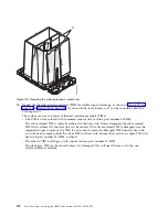
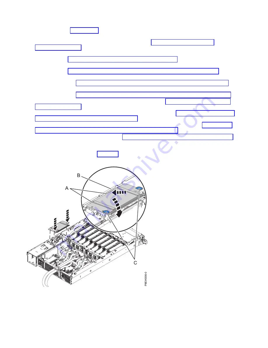
Install the power riser air baffle. Ensure that the holes in the baffle align with the pins on the system.
Using the blue tabs (C), insert the edge (A) of the baffle into the side of the system (B). Then snap
the baffle down into place. See Figure 141.
Preparing the system for operation after removing and replacing the system
backplane in an air-cooled 8335-GTB
To prepare an air-cooled system for operation after replacing a system backplane, complete the steps in
this procedure.
Figure 141. Installing the power riser air baffle
120
Power Systems: Servicing the IBM Power System S822LC (8335-GTB)
Содержание S822LC
Страница 1: ...Power Systems Servicing the IBM Power System S822LC 8335 GTB IBM ...
Страница 2: ......
Страница 3: ...Power Systems Servicing the IBM Power System S822LC 8335 GTB IBM ...
Страница 16: ...xiv Power Systems Servicing the IBM Power System S822LC 8335 GTB ...
Страница 204: ...188 Power Systems Servicing the IBM Power System S822LC 8335 GTB ...
Страница 242: ...226 Power Systems Servicing the IBM Power System S822LC 8335 GTB ...
Страница 243: ......
Страница 244: ...IBM ...


