© Copyright IBM Corporation 2019, 2020, 2021 Customer Install Guide, 1U Chassis
21
•
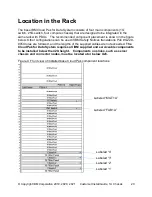
Chassis #1 - Install this 1U server (marked #1) one rack unit (1U) above the
bottom of the rack.
•
Chassis #2 - Install this 1U server (marked #2) 1U above Chassis #1.
•
Chassis #3 - Install this 1U server (marked #3) 1U above Chassis #2.
•
Chassis #4 - Install this 1U server (marked #4) 1U above Chassis #3.
•
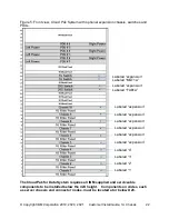
25G Switch - The 25G switch (marked # Fab1A) should be installed above the
top-most server. You may install the 25G switch in any convenient location.
(see
Figure 2 for recommended switch location, U25)
•
1G Switch - The 1G switch (marked # MGT1A) should be installed above the
25G switch. You may install the 1G switch in any convenient location.
(see
Figure 2 for recommended switch location, U28)
•
PDUs
– Install horizontally at U33/U34 for easy cable routing and service access.
Additional PDUs should be installed above the PDUs at locations U35/U36.
•
Other components should be installed per the specific install guide included with
those components.
Installation Notes:
•
Servers are preconfigured for their specific slots (1, 2, 3 & 4) in the rack
and they must not be mixed up
•
If you intend to expand your system, you may want to leave enough space
to install additional expansion chassis and switches at a later date. Expansion
chassis and switches are ordered separately. Expansion chassis and switches
can be racked in any order, but the preferred locations are shown in the figure
below.
•
Expansion chassis and switches
are marked “EXPANSION”.
Содержание 3455-D3E
Страница 12: ... Copyright IBM Corporation 2019 2020 2021 Customer Install Guide 1U Chassis 12 L003 or or ...
Страница 32: ... Copyright IBM Corporation 2019 2020 2021 Customer Install Guide 1U Chassis 32 Figure 15 Add Cables ...
Страница 38: ... Copyright IBM Corporation 2019 2020 2021 Customer Install Guide 1U Chassis 38 Regulatory and Compliance ...
Страница 45: ... Copyright IBM Corporation 2019 2020 2021 Customer Install Guide 1U Chassis 45 ...

