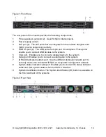


© Copyright IBM Corporation 2019, 2020, 2021 Customer Install Guide, 1U Chassis
30
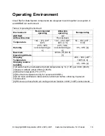
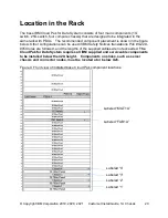
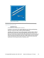
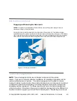
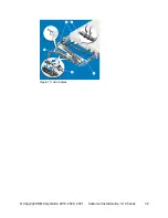
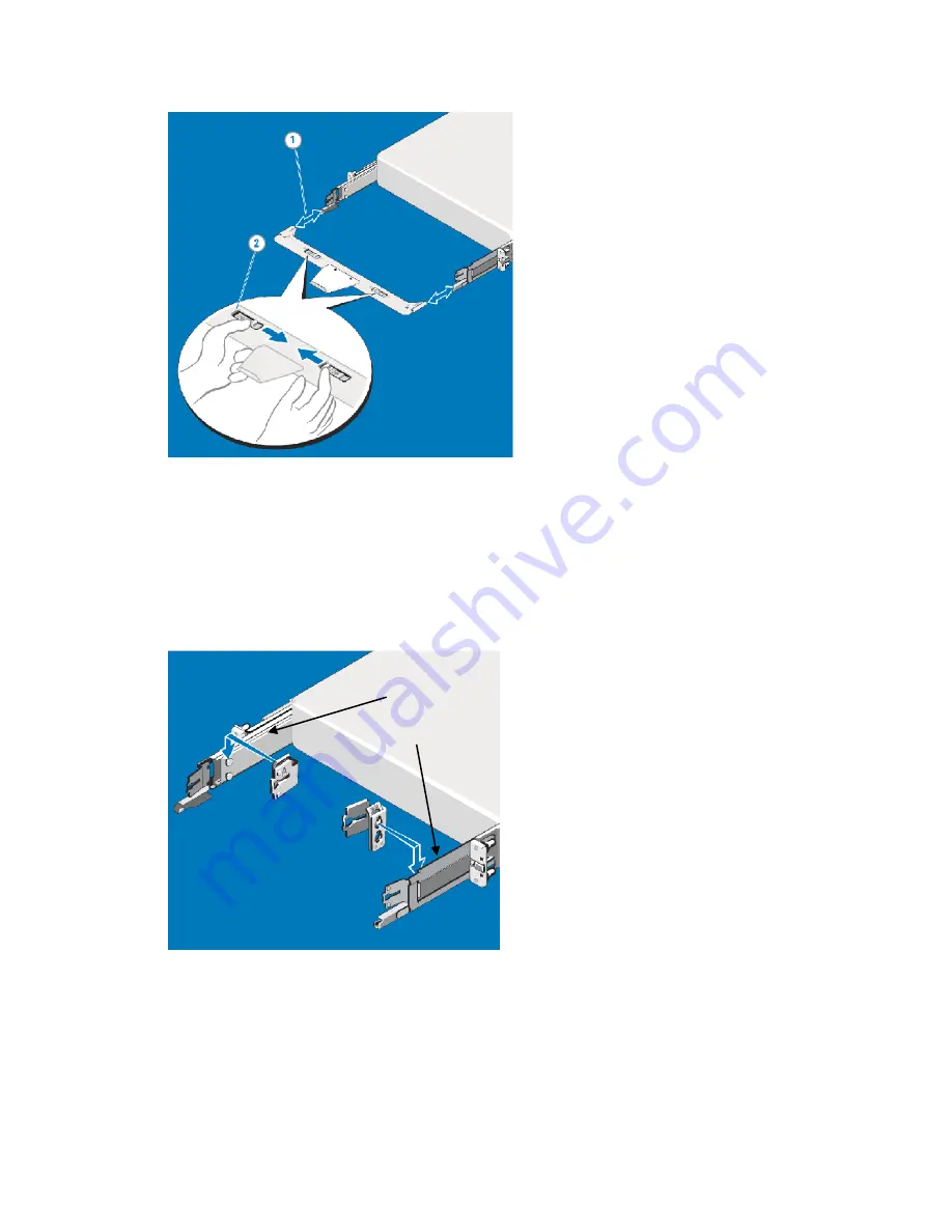
Figure 12. Cable management tray installation
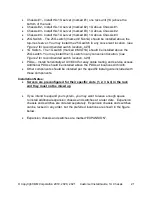
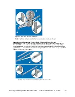
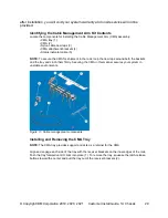
Installing the CMA Attachment Brackets
NOTE:
Attach the CMA to the left mounting rail (SIDE A) since that is the side opposite of the
power supplies. Mounting to SIDE B requires the CMA to be disconnected in order to remove the outer
power supply. Always remove the tray before removing the power supplies. Install the CMA attachment
bracket at the back of the SIDE A side rail. Align the holes on the bracket with the pins on the slide rail
and push the bracket downward until it locks into place.
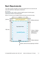
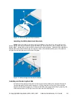
Figure 13. Cable management bracket installation
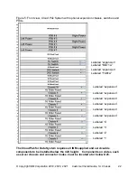
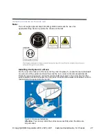
Installing and Removing the CMA
At the back of the system, fit the latch on the front end of the CMA on the innermost bracket of
the slide assembly until the latch engages (1). Fit the other latch on the end of the outermost
bracket until the latch engages (2). To remove the CMA, disengage both latches by pressing the
CMA release buttons on the top of the inner and outer latch housings (3).
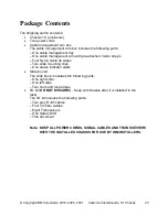
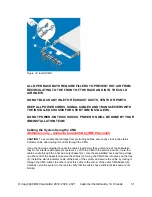
Side A
Side B
Содержание 3455-D3E
Страница 12: ... Copyright IBM Corporation 2019 2020 2021 Customer Install Guide 1U Chassis 12 L003 or or ...
Страница 32: ... Copyright IBM Corporation 2019 2020 2021 Customer Install Guide 1U Chassis 32 Figure 15 Add Cables ...
Страница 38: ... Copyright IBM Corporation 2019 2020 2021 Customer Install Guide 1U Chassis 38 Regulatory and Compliance ...
Страница 45: ... Copyright IBM Corporation 2019 2020 2021 Customer Install Guide 1U Chassis 45 ...