


Page 91
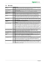
Glossary ctd. (2)
Switchover point
81
Defined switching threshold for switchover from one
load level [64]
to an other depending on the input
signal level.
Virtual interlock (safety) system
86
If control via à
Communication interface [13]
was selected, software is used to place a logical switch in
series with the hardware interlock (safety) system. This switch can be opened and closed via à
Software
commands [12]
. If the hardware interlock (safety) system is closed and the switch is opened via software
control command, steam production is stopped and the unit is placed in "Remote switch-off" status.
Hygiene flushing
87
For hygiene reasons, the controls of the VDI 6022 are set so that flushing must take place at intervals of not
longer than 48 h. An interval of < 48 h can be set. The factory setting is 24 h.
Pressure reduction
88
To relieve the pressure system, the solenoid valves to the nozzle sections are opened for the time set in the
"Pressure_reduction_duration" parameter while the water supply solenoid valve is closed and the high
pressure pump is switched off.
Supply voltage
89
The units are designed for connection to supply voltage ranges (e.g. 380 to 415 VAC in case of a 400 VAC
unit, s. name plate)
Unit name
90
Here, "Unit 1" is entered by default.
Recording
93
The control can record 10 data sets internally on a rolling basis. Snapshots of the unit status are carried out
at intervals of 10 s, which can be helpful for troubleshooting. When the storage space is filled, a new set of
data overrides the oldest entry. The complete record can be saved to a USB stick with NTFS formatting.
PI
controller
96
Internal controller with control characteristics which contain a
P
roportional part and an
I
ntegral part. Both
parts are variable as parameter settings.
Digital input
97
Digital input on the mainboard and on the relay boards for switching functions. A logical meaning (e.g. timer
start) is assigned to the digital input via the
Digital_input_function [98]
parameter. The digital input must be
wired on-site in accordance with its use, e.g. with a
Pushbutton [106]
or a
Switch (NO) [102]
against
the 20 VDC on terminal 8 on the mainboard terminal strip ST08 or the terminal strip ST05 on the other
available boards. When the
20 VDC voltage is applied (short-term via a
Pushbutton [106]
or permanent
via a
Switch (NO) [102
] ), as required in accordance with
Digital_input_function [98]
parameter setting),
the switching function is carried out.
Digital_input_function
98
Determines which function will be executed if the
Digital input [97]
on the mainboard or one of the relay
boards is activated by applying an
Auxilliary voltage [105],
either short-term (via a push-button) or
permanent (via a switch).
Load shedding
101 Load shedding can be set up by assigning the
Function_digital_input [98] "Power limitation" to the
Digital input [97]
. When the
Digital input [97]
is then then connected to an
Auxilliary voltage [105]
by
means of a
Switch (NO) [102]
,
Max. humidification output [43]
is reduced by the percentage set up in
the "
Δ
power limitation" parameter. After withdrawel of the voltage normal operation is reestablished.
Switch (NO)
102 Electrical switch with
N
ormally
O
pen contacts
Auxiliary voltage
105 DC voltage in the range of 5…20V for activating the
Digital input [97]
via a
Pushbutton switch [106]
or a
Switch [102]
. +20 VDC is available on Pin 3 of ST08 (mainboard) or ST05 (relay board). The auxiliary
voltage is required to switch the
Digital_input [97]
on the mainboard or a relay board in order to trigger the
function defined by setting the
Function_digital_input [98]
(e.g. switch on ECO mode).
Push button
106 Electrical switch for momentary action
Frequency converter
108 Electronical device for control of the asynchronous motor of the pump group. Pump speed determines the
pump pressure.
Pressure controller
109 Integrated
PI controller
[96
] for pressure control of the system. The control signal of the pressure
controller is effective on the
Frequency converter [108]
and - consequently - on the pump speed.
Nozzles (status)
110 The spray image of the nozzles may change due to the faintest contamination. In that case cleaning is
adequate in a ultrasonic bath (s. maintenance section). If the nozzles are clogged with time by lime deposits,
the inner system pressure may rise as compared to the pressure at the time of commisioning without
showing any external signs. Control can detect this variation by means of an algorithm.
Load
111 The spray system (e.g. the vortex modules) can be segmented into nozzles that allow for a more delicate
humidification control by phased control. The nozzle sections are referred to as "loads" in this document.
The switch-over points between the loads are parameterizable.
Supply air humidification
112 Normal system operation
Input signal limitation
113 When using an external controller, the full swing of the
internal actuator signal [42]
may be assigned to a
cut-off window of the external controller signal swing. By doing so, a better control resolution may be
achieved in a particular region. The cut-off window is defined by the parameters "Limitation_ext._X1" (lower
value) and "Limitation_ext._X2" (upper value) .
Combined system
114 This particular made-to-order-system allows the switch from
Supply air humidification [112
] to
Exhaust air cooling [62
]. Switching is usually controlled by the Building Control System via a relay contact
or through an other on-site switching device.
Содержание HPS250
Страница 24: ...Seite 24 6 3 1 Dimensions and mounting instructions ...
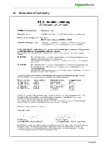
Страница 85: ...Seite 85 16 Declaration of Conformity ...


