

Page 34
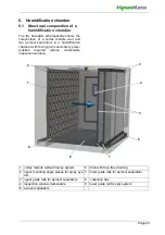
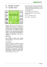
11. Description of control
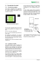
11.1 General description
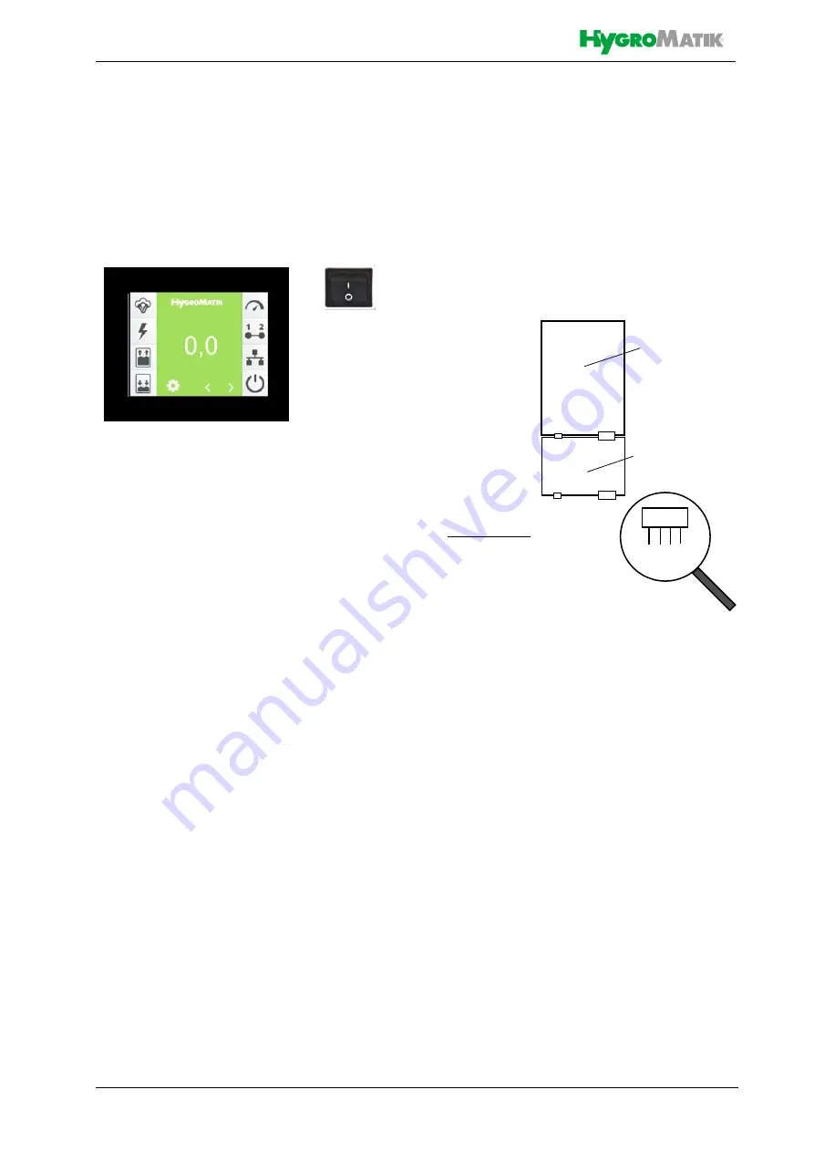
The control is integrated into the high-pres-
sure system housing and is operated via a
3.5" graphic display (touch-screen) on the
front side of the unit
.
The only other operating element is the main
switch whose positions are assigned as fol-
lows:
Pos. "0": The unit is switched off
Pos. "I": The unit is switched on and the con-
trol is active
By changing the parameters, the operator
can adapt the control to the system specifica-
tions and the special characteristics relating
to the use of the unit.
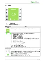
Operation of the control is described in detail
in section 12.
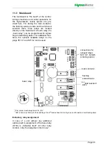
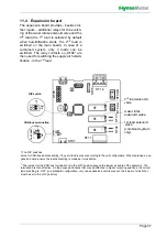
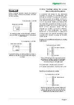
11.2 Layout of control
The control consists of the 3,5“ display, the
mainboard and an expansion board that is
attached to the mainboard. The mainboard
can be expanded for additional functions with
additional optional relays in DIN rail format.
The DIN rail relays are connected via cables
with plug. Up to 2 additional relay modules
can be used, with 2 relays each.
The external circuitry for the control voltage
and the interlock (safety) system (wired to the
X1 terminal block) are fed to the control elec-
tronics via plug ST1.1 of the expansion board
and are looped from there to the mainboard.
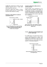
Fusing of the control voltage is made on the
mainboard by 2 2.5 A fast-blow fuses (F1,
F2).
The low voltage supply power für expansion
board is channeled from the mainboard to the
expansion board through plugs ST11.1 and
ST08. This connection is also used for the
bidirectional serial data exchange between
the logic modules on the two boards.
*)
The expansion board is referred to as „Cyl-
inder expansion“ in other sections of this
manual due to internal reasons.
Touchscreen and main switch
ST1
N
L
1
2
ST1.1
ST1.2
ST08
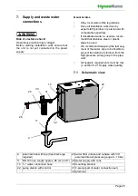
Connections
L,N: 230 VAC control voltage
1,2: Interlock (safety) system
ST1.1
ST11.1
Mainboard
Expansion
board
*)
ST1
(via teminal block X1):
Содержание HPS250
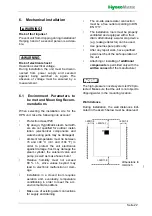
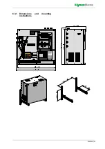
Страница 24: ...Seite 24 6 3 1 Dimensions and mounting instructions ...
Страница 85: ...Seite 85 16 Declaration of Conformity ...


