Page 26
7.2 Water inlet
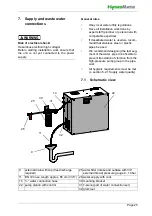
For the supply water feed, a connection piece
with a ¾
“ external thread is located on the
left unit housing wall.
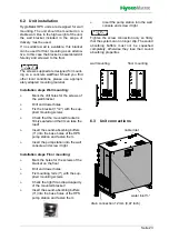
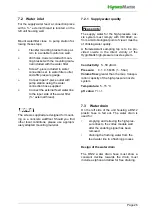
Mount waterfilter close to pump station fol-
lowing these steps:
»
Transfer mounting bracket hole pat-
tern to a suitable location on wall.
»
drill holes, dowel and attach moun-
ting bracket with the mounting mate-
rial included with the water filter.
»
Screw T-piece included in water
connection set to water filter outlet
and affix pressure gauge.
»
Connect open T-piece outlet with
pump station using the water
connection hose supplied.
»
Connect the external feed water line
to the input side of the water filter
(¾ “ external thread).
The screws supplied are designed for mount-
ing on a concrete wall/floor. Should you find
other local conditions, please use appropri-
ately adapted mounting material.
7.2.1 Supply water quality
The supply water for the high-pressure noz-
zle system must comply with VDI 6022; i.e.
from a microbiological point of view it must be
of drinking water quality.
A flameresistant sampling tap
is to be pro-
vided on-site in the direct vicinity of the
HygroMatik high-pressure nozzle system.
Conductivity:
5...50 µS/cm
Pressure:
0.1...0.5 MPa (1...5 bar)
Volume flow:
greater than the max. transpo-
ration capacity of the high-pressure nozzle
system
Temperature:
5...15 °C
pH value:
7 +/-1
7.3 Water drain
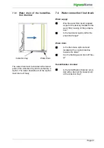
On the left side of the unit housing a DN12
plastic hose is fed out. The water drain is
used for:
•
emptying and relieving the high-pres-
sure lines to the vortex module wall
after the enabling signal has been
removed
•
draining the flushing water from the
feed water line in a flushing process
Design of the water drain
The DN12 water drain hose must show a
constant decline towards the drain, must
include a siphon and allow for free draining.
NOTICE
Please note
Содержание HPS250
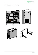
Страница 24: ...Seite 24 6 3 1 Dimensions and mounting instructions ...
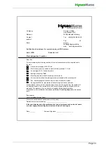
Страница 85: ...Seite 85 16 Declaration of Conformity ...


