Page 64
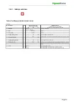
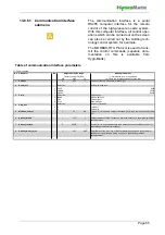
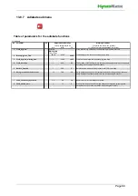
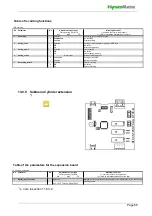
13.8.6 Functions submenu
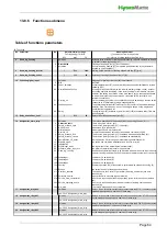
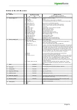
Table of functions parameters
10: Functions
No. Parameter
No.
Meaning/Comment
[ ] explains the term in the glossary
Min
Max
FS
[ ] refers to a related explanation of the term
4 Dead_leg_flushing
Solenoid valve of the water inlet and pump\flushing valve are switched on and off
in parallel for dead leg flushing [27].
0
Flushing of dead-end line [27] is not carried out
1
Perform dead leg flushing [27] as required (semi-automatic or fully automatic,
depending on device/plant)
5 Dead_leg_flushing_interval
1
5760
1440
Waiting period until start of flushing of dead-end line [27] [min]
6 Dead_leg_flushing_active
1
600
90
Duration of flushing of dead-end line [27] [s]
12 Function_digital_input
Mapping of digital input function [98] to mainboard
0 Not
used
40
Activated digital input [97] by a switch (NO) switches power limitation on for load
shedding [101]
50
If the digital input is activated (switch towards auxiliary voltage closed), exhaust
air cooling operation is enabled. In the factory setting for combination systems,
however, the setting is not made on the main board, but on the expansion board
to which the relevant switch must also be connected (ST05, terminal 8; see
terminal connections).
51
On the combination system, the exhaust air cooling is switched on with the switch
connected to ST08 terminal 8 (single-stage operation)
62
The activated digital input [97] monitors the (NC) contact of an external leakage
detector. If the contact opens, an error message is shown on the display and
humidification is switched off
90
The digital input [97] activated by a switch (NO) [102] activates a relay if this has
been assigned.
15 Delay_humidificat._notif.
0
3600
60
Delay of Humidifying message [s]
[74]
16 Assignment_main_relay
The relay is energised for a message (M) or a switching function (S), if ...
0
There is any kind of error (M)
1
The interlock (safety) system [11] is open (M)
2
No demand [5] is present (M)
3
Steam production is in progress (M)
5
A remote shutdown was carried out via software command [12] (M)
6
The interlock (safety) system [11] is switched via an additional relay (M)
7
The interlock (safety) system [11] is switched as standard (M)
8
A dropout delay [74] is to be generated following humidification (S)
12
the device has completed initialization and is not in error (M)
13
20
the digital input of the motherboard is activated (M)
38
the minimum water inlet pressure is not reached.
68
An additionally installed relay is to be actuated, which switches the input solenoid
valve for flushing the dead-leg line if the interlock (safety) system is not closed (S)
150
Load level 1 is switched (S)
151
Load level 2 is switched (S)
152
Load level 3 is switched (S)
154
Summer operation [62] of the system is performed with exhaust air cooling (S)
155
the solenoid valve for the bypass is switched.
211
The value set in the Control 21 parameter (Humidity_notification) has been
reached (M)
270
A general service message is generated (M)
274
A service is required after the max. operating cycles for K1 have been reached
(M)
283
A service is required after the maximum number of working hours has been
reached (M)
284
The relay is not used and is not controlled.
17 Assignment_relay
K20
Relay 1 is one of the top-hat rail relays connected to the ST10.1 connector on the
mainboard; assignment is same as for base relay
Selection
Off
Power_limitation
Humidification/Cooling
Cooling_on
Leakage_sensor
Adjustment/value range
Factory setting (FS) Bold
Selection
Deactivated
Activated
Remote_off
Safety_interlock_ELV
Safety_interlock_closed
Humdification_off_delay
Standby_signal
Initialization
Relay
Selection
Collective_fault
Safety_interlock_open
No_Demand
Humidification
Cooling
Bypass
Humidity_reached
Collective_service
Service_main_contactor K1
Service_operating_hours
Digital input_active
Pressure_water_input_min
Dead_leg_flushing
Loadstage 1
Loadstage 2
Loadstage 3
Not_used
Selection
see: 10-16 Assignment_main_relay
18 Assignment_relay
K21
Relay 2 is the second of the top-hat rail relays connected to the ST10.2 connector
on the mainboard; assignment is same as for base relay
19 Assignment_relay
K22
Relay 3 is one of the top-hat rail relays connected to the ST10.2 connector on the
mainboard; assignment is same as for base relay
20 Assignment_relay
K23
Relay 4 is the second of the top-hat rail relays connected to the ST10.2 connector
on the mainboard; assignment is same as for base relay
see: 10-16 Assignment_main_relay
Selection
see: 10-16 Assignment_main_relay
Selection
see: 10-16 Assignment_main_relay
Selection
Содержание HPS250
Страница 24: ...Seite 24 6 3 1 Dimensions and mounting instructions ...
Страница 85: ...Seite 85 16 Declaration of Conformity ...

