background image

-1500/-1700 IHT

43

NO. DESCRIPTION

1 Main 

Housing 

Assembly

2A R.H. 

Housing 

Assembly

2B 

Brake Bolt Kit

3 Center 

Section 

Assembly

4 Spacer
5 Lip 

Seal

Wire Retaining Ring

7 Retaining 

Ring

8 Ball 

Bearing

10 Variable 

Swashplate

11 Thrust 

Bearing

12 Input 

Shaft

13 Block 

Thrust 

Washer

14 Block 

Spring

15 

10cc Cylinder Block Assembly

21 

21cc Cylinder Block Assembly

24 

Output (Motor) Shaft

25 Thrust 

Bearing

26 Control 

Arm

27 Spacer
28 

19T  Pinion Gear

30 Slot 

Guide

31 Trunnion 

Arm

32 Trunnion 

Bushing

33 Lip 

Seal

34 Return 

Arm

35 Actuating 

Arm

36 

Stud 5/16 - 24

38 Bypass 

Plate

39 Bypass 

Actuator

40 Lip 

Seal

41 Bypass 

Arm

42 Retaining 

Ring

43 Pin
44 Screw 
46 Neutral 

Spring

48 Adjusting 

Puck

49 

Auxiliary Charge Pump Kit

50 

Screw ,  Self-Tapping

51 Lower 

Cover 

52 Gerotor 

Assembly

53 O-Ring
54 

Auxiliary Manifold Kit

55 Filter 

Kit

57 

Retainer, Motor Bearing

58 Pin, 

Carrier

59 

15T  Planet Gear

60 

67T Spur Gear

61 

21T Sun Gear

62 Planet 

Thrust 

Plate

63 

51T Ring Gear

64 Planetary 

Carrier

65 

Miter Gear, Differential (SPLINED)

66 

Miter Gear, Differential 

67 

Shaft , Differential 

68 Differential 

Thrust 

Plate

69 Flange 

Bearing

71 Washer
73 

Hex Jam Nut, 5/8 - 18

74 

Ball Bearing 6205-1

75 

Seal, 1” ID X 2.0472” X 0.375”

76 Shaft, 

Axle

77 Washer
79 Gasket 

Material/Sealant

80 

Torx Head Screw 5/16 - 18

81 Needle 

Bearing

82 Washer
83 Retaining 

Ring

84 Lip 

Seal

85 Brake 

Disc

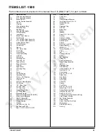
ITEMS LIST -1700

Part numbers are not provided in this manual. See CD (BLN-51427) for part  numbers.

NO. DESCRIPTION

86 Washer
87 Washer
88 

Screw 5/16 - 24 X 1-3/4

89 Bearing
90 Spacer, 

Locating

92 Countersunk 

Screw 

95 

Nut, Hex Lock 5/16 - 24

96 Sleeve 

Bearing

97 20W50 

Oil 

102 Torque 

Bracket

103 Pulley
104 Fan
106 Spacer, 

Trunnion

107 Screw 
108 Plug
109 Vent 

Bushing

110 Fitting 

Kit 

111 Cap-Vent 

Assembly

113 Hose/ 

Fitting 

Assembly

115 Jam 

Nut

116 Retaining 

Ring

117 

Std Hlds Pins

118 

Hub Assembly 7/16 - 14

119 

Nut, Hex 3/4 - 16

120 Puck, 

Brake 

121 

Bolt, 1/4 - 20 X 1.25

122 Brake 

Yoke

124 Arm, 

Brake

125 Pins, 

Brake

128 Nut, 

Castle

129 Cotter 

Pin

130 Spacer
131 Puck 

Plate

132 

Bolt, 1/4 - 20 X 2.25

133 

Wheel Stud 7/16-14

139 Washer
141 

Spring, Brake Arm Bias

142 

Hex Lock Nut 5/16 - 18

143 

Bolt 5/16 -15 X 2.5

145 Relief 

Spring

146 Ball
151 

Compression Spring Brake Anti-Drag

153 Plug, 

Straight 

Thread

155 Fan/ 

Pulley 

Assembly

157 Screw 

O-Ring

162 Shim
163 Pin
164 Valve 

Body

165 O-Ring
166 Spring
167 Ball
168 

Screw, Shoulder Torx Head

170 Cam, 

Stationary

171 Cam, 

Rotating

172 Washer
173 Load 

Plate

175 Dog, 

Engagement

177 Washer 

Guide

178 Cam, 

Actuating

179 Shaft
180 Sleeve
181 Handle, 

Actuating

182 Ring, 

Retaining

183 O-Ring
184 O-Ring
203 Seal 

Kit

208 

Auxiliary Relief Valve Kit

209 

Charge Relief Kit

210 Nut, 

Lug

Содержание 310-1500

Страница 1: ...tegrated Hydrostatic Transaxle Service and Repair Manual BLN 52178 December 2008 Digitally signed by WMV Dresden DN cn WMV Dresden c DE o WMV Dresden email noreply wmv dresden de Date 2017 01 26 09 49 46 01 00 WMV Dresden ...

Страница 2: ...Purging Procedures 14 Repair 15 General Instructions 15 Required Tools 15 Torque Specifications 15 Transaxle Removal 15 Limited Disassembly 15 How To Use This Manual 16 Brake Assembly 17 18 Bypass Assembly 19 Control Assembly 20 21 Seal Kit Replacement 22 Torque Bracket Assembly 23 Fan and Pulley Assembly 24 Input Shaft Assembly 25 Auxiliary Pump 26 Charge Pump Assembly 27 Lower Housing FIlter Man...

Страница 3: ... a good shop practice that your service area be equipped with the proper tools and the mechanics be supplied the latest information available All repair procedures il lustrated in this guide are suggested but pre ferred methods of repair Repair procedures require that the transaxle unit be removed from the vehicle This is not a certification test or study guide for a certification test If a techni...

Страница 4: ...plate with a direct proportional displacement control Reversing the direction of the swash plate reverses the flow of oil from the pump and thus reverses the direction of the motor output rotation The pump and motor are of the axial piston design and utilize spherical nosed pistons which are held against a thrust race by internal compression springs The 1500 1700 series transaxles have a self cont...

Страница 5: ... 1500 1700 IHT 3 Figure 1 1500 Hydraulic Schematic HYDRAULIC SCHEMATIC Figure 2 1700 Hydraulic Schematic Figure 3 1700 Hydraulic Schematic with Auxiliary Pump ...

Страница 6: ...gned into the product for lubrication purposes around pistons under the rotating cylinder blocks etc This lost fluid returns Figure 4 1500 Hydraulic Flow Illustration to the transmission housing and must be made up in the loop A charge pump is included on the IHT to supply this makeup flow The make up flow is controlled or directed by the check valves Each check valve will either be held opened or...

Страница 7: ... 1500 1700 IHT 5 HYDRAULIC SCHEMATIC Figure 5 1700 Hydraulic Flow Illustration ...

Страница 8: ...6 1500 1700 IHT EXTERNAL FEATURES 1500 AND 1700 ...

Страница 9: ...II IIII III III I II IIII 8 328 T1 476 Made in U S A Year Built Date Julian day of year Type of Product and Build Information Serial Number unique number for that model for that day OEM Model Number Hydro Gear Number 312 1700 Model Number Model Reference Number 1500 1700 Overall Transaxle Reduction 24 6 1 24 6 1 Input Speed rpm 3000 max 1800 min 3600 max 1800 min Maximum Tire Diameter 20 in 508 mm...

Страница 10: ...ver use compressed air to clean debris from yourself or your clothing TOOL SAFETY Use the proper tools and equipment for the task Inspect each tool before use and replace any tool that may be damaged or defective WORK AREA SAFETY Keep the work area neat and orderly Be sure it is well lit that extra tools are put away trash and refuse are in the proper containers and dirt or debris have been remove...

Страница 11: ...ine RPM low Control linkage bent or out of adjustment Brake setting incorrect Drive belt slipping or pulley damaged Oil level low or contaminated oil Excessive loading Bypass assembly sticking Air trapped in hydraulic system Adjust to correct setting Repair or replace linkage Adjust brake to proper setting Repair or replace drive belt or pulley Fill to proper level or change oil Reduce vehicle loa...

Страница 12: ...ccur Slippage can cause low input speed to the transaxle 4 Inspect the transaxle cooling fan for bro ken or distorted blades and remove any obstructions grass clippings leaves dirt etc 5 Inspect the axle parking brake and vehicle linkage to insure proper actuation of the parking brake 6 Inspect the vehicle control linkage to the directional control arm on transaxle Also insure the control arm is s...

Страница 13: ...NGE This transaxle is factory filled and does not require a regular oil change In the event of oil contamination or degradation an oil change may improve performance Using the transaxle removal procedure from Section 5 Page 15 remove the transaxle and drain the oil from the top fluid fill port Fill unit per Table 3 reinstall the transaxle and perform the purging procedures Page 14 In the event a f...

Страница 14: ...ecuring the brake castle nut 2 Insert a 0 015 381 mm feeler gage be tween the brake disc and top brake puck and then set the brake by tightening or loosening the castle nut 3 Adjust brake gap to 0 015 381 mm clear ance 4 Install the cotter pin to secure the castle nut and then install the brake arm bias spring ...

Страница 15: ...rer s OEM s control linkage at the control arm Refer to Figure 9 WARNING Do not attempt any adjustments with the engine running Use extreme caution while inspecting all vehicle linkage Follow all safety procedures outlined in the vehicle owner s manual 3 Start the engine and increase the throttle to full engine rpm 4 Check for axle rotation If the axles do not rotate go to Step 5 If the axles rota...

Страница 16: ...dures should be per formed with the vehicle drive wheels off the ground then repeated under normal operating conditions 1 With the bypass valve open and the engine running slowly move the directional control in both forward and reverse directions 6 to 10 times as air is purged from the unit the oil level will drop and bubbles may appear in the oil After stopping the engine add oil as necessary Fil...

Страница 17: ...pair of the 1500 or 1700 IHT is provided in Table 4 Page 17 TORQUE SPECIFICATIONS Torque specifications for fasteners used on the 1500 and 1700 IHT are provided in Table 5 TRANSAXLE REMOVAL It is necessary to remove the 1500 or 1700 from the vehicle before performing the repair procedures presented in this section Use the following procedure to prepare the unit for re moval from the vehicle 1 With...

Страница 18: ...bly summary a complete exploded views and items lists are provided Sockets 3 8 Drive 7 16 1 2 13 16 1 2 Drive 9 16 15 16 1 1 8 8 Internal Torx Drive 10 Internal Torx Drive Socket Drivers 3 8 1 2 Combination Wrenches 7 16 1 2 9 16 13 16 15 16 1 1 8 Table 4 Required Tools Operation Torque Item Description Center Section Screws Item 44 525 700 lb in 59 79 Nm 44 Screw Lower Housing Screws Item 50 135 ...

Страница 19: ...ve lower bolt 132 washer 139 and spacer 130 which secure the brake yoke assembly 122 6 Remove brake yoke assembly 122 puck plate 131 and outer brake puck 120 7 Remove brake disc 85 and inner brake puck 120 Figure 12 Brake Assembly REF Part Name 129 Cotter Pin 130 Spacer 131 Puck Plate 132 Bolt 139 Washer 141 Brake Arm Bias Spring 151 Anti Drag Compression Spring REF Part Name 2 Right Hand Housing ...

Страница 20: ...r 139 and bolt 132 to secure the brake yoke assembly 122 6 Install brake anti drag compression spring 151 and two brake pins 125 7 Install brake arm 124 onto brake yoke as sembly 8 Install washer 77 and castle nut 128 9 Insert a 0 015 381 mm feeler gage be tween brake disc 85 and outer brake puck 120 Adjust the brake by turning castle nut 128 until it is snug but not tight against the feeler gage ...

Страница 21: ...Remove bypass arm 41 3 Remove bypass lip seal 40 INSPECTION 1 Inspect bypass arm 41 for wear ASSEMBLY 1 Install bypass lip seal 40 See Page 25 for instructions 2 Install bypass arm 41 3 Install retaining ring 42 REF Part Name 40 Lip Seal 41 Bypass Arm 42 Retaining Ring Figure 14 Bypass Assembly ...

Страница 22: ...2 Inspect trunnion arm lip seal 33 and replace if necessary See page 22 for re placement instructions ASSEMBLY CONTROL ARM ASSEMBLY 1 Install new trunnion arm lip seal 33 into main housing 1 See page 22 for instruc tions 2 Install stud 36 per Table 5 Page 16 3 Install control arm 26 onto trunnion arm 31 and stud 36 4 Install trunnion spacer 106 and lock nut 95 per table 5 Page 16 onto the trunnion...

Страница 23: ...rm 31 Trunnion Arm 32 Trunnion Bushing 33 Lip Seal 34 Return Arm 36 Stud 46 Spring 48 Adjusting Puck Figure 15 Control Arm Assembly REF Part Name 87 Washer 88 Screw 89 Bearing 90 Locating Spacer 92 Countersink Screw 95 Locknut 106 Trunnion Spacer ...

Страница 24: ...ove AXLE SEAL 1 The seal 75 can be replace by following steps 2 6 of the procedure used to replace the input seal 2 Install the retaining ring 116 and make sure it is fully seated in its groove MOTOR SHAFT SEAL 1 Remove the brake assembly See Pages 17 18 2 The seal 84 can be replaced by following steps 3 6 of the procedure used to replace the input shaft TRUNNION SEAL 1 Remove the control arm and ...

Страница 25: ...102 2 Remove torque bracket 102 from main housing 1 ASSEMBLY 1 Install torque bracket 102 onto main hous ing 1 2 Install lock nut 142 and bolt 143 to se cure torque bracket 102 to main housing 1 Reference Table 5 Page 16 for torque values REF Part Name 1 Main Housing 102 Torque Bracket 142 Lock Nut 143 Bolt Figure 17 Torque Bracket Assembly ...

Страница 26: ...roken and or damaged blades If necessary to replace fan 104 remove fan 104 from pulley 103 ASSEMBLY 1 Install fan pulley assembly 104 and 103 onto input shaft 12 2 Secure fan pulley assembly 104 and 103 onto shaft 12 by installing slotted washer 107 and jam nut 115 per table 5 Page 16 REF Part Name 1 Main Housing 12 Input Shaft 103 Pulley 104 Fan 107 Slotted Washer 115 Jam Nut Figure 18 Fan and Pu...

Страница 27: ...ve washer 13 from the input shaft bore INSPECTION 1 Inspect bearing 8 for damage and if necessary replace bearing remove wire retaining ring 6 and bearing 8 from input shaft 12 ASSEMBLY 1 Carefully install washer 13 onto top of spring in the input shaft bore 2 Press bearing 8 onto input shaft 12 and secure by installing wire retaining ring 6 3 Install input shaft assembly items 12 8 and 6 into inp...

Страница 28: ...ve the cover 54 2 Remove o ring 53 gerotor assembly 52 shim 162 and pins 163 INSPECTION 1 Inspect gerotor assembly 52 pump cover 54 for damage or excessive wear ASSEMBLY 1 Install gerotor 52 with new o ring 53 onto input shaft 12 not shown 2 Install new O ring 53 into pump cover 54 3 Install pins 163 and shim 162 onto the pump cover 54 4 Install cover 54 and secure by installing two screws 29 per ...

Страница 29: ...ure charge pump cover 54 by installing two screws 29 per Table 5 Page 16 LOWER HOUSING FILTER ASSEMBLY 1500 Refer to Figure 22 DISASSEMBLY 1 Remove the eleven housing screws 50 and lower cover 51 and remove sealant from the housing and lower cover 51 2 Remove filter 55 from the center section assembly 3 not shown INSPECTION 1 Inspect filter 55 replace if necessary NOTE Filter replacement is sugges...

Страница 30: ...g 145 and ball 146 4 Remove filter 55 and charge manifold 56 5 Remove o ring 144 INSPECTION 1 Inspect filter 55 and manifold 56 replace if necessary NOTE Filter replacement is suggested 2 Inspect o ring 144 and screw O rings 157 ASSEMBLY 1 Install o ring 144 onto center section as sembly 3 refer to Figure 27 2 Install filter 55 and charge manifold 56 3 Install spring 145 and ball 146 4 Install scr...

Страница 31: ...charge manifold 56 3 Remove o ring 144 INSPECTION 1 Inspect filter 55 and manifold 56 replace if necessary NOTE Filter replacement is suggested 2 Inspect o ring 144 ASSEMBLY 1 Install o ring 144 onto center section as sembly 3 refer to Figure 27 2 Apply sealant to filter 55 before assembling with charge manifold 56 3 Install filter 55 and charge manifold 56 4 Dry fit lower cover 51 on housing usin...

Страница 32: ...g 1 16 See page 22 for axle shaft seal removal INSPECTION 1 Inspect all gears for excessive wear or dam age and replace if necessary 2 Remove all sealant from both housings and inspect seal lands for damage when clean ing 3 If bevel gear 65 needs replacing remove jam nut 73 from axle shaft 76 ASSEMBLY 1 If necessary install L H Axle shaft assem bly 76 into main housing 1 If necessary reassemble ax...

Страница 33: ...ned with the sun gear 61 Mate the bevel gear 65 on the end of the RH axle shaft with the bevel gears 66 in the differential assembly Continue to sup port the RH axle shaft 11 Install the planetary thrust plate 62 12 Install the 64T spur gear 60 onto the 21T sun gear 61 13 Slide washer 71 onto axle shaft 76 14 Install the two housing pins 117 into the main housing 1 15 Apply a bead of sealant to th...

Страница 34: ... 177 relief springs 145 dogs 175 load plate 173 washer 172 rotating cam 171 and stationary cam 170 INSPECTION 1 Inspect all gears for excessive wear or dam age and replace if necessary 2 Remove all sealant from both housings and inspect seal lands for damage when clean ing 3 If bevel gear 65 needs replacing remove jam nut 73 from axle shaft 76 ASSEMBLY 1 If necessary install L H Axle shaft assembl...

Страница 35: ... 61 Mate the bevel gear on the end of the RH axle shaft with the bevel gears 66 in the differential assembly Continue to sup port the RH axle shaft 12 Install the planetary thrust plate 62 13 Install the 64T spur gear 60 onto the 21T sun gear 61 14 Slide washer 71 onto axle shaft 76 15 Install the two housing pins 117 into the main housing 1 16 Apply a bead of sealant to the main housing 1 See pag...

Страница 36: ...Inspect running surface of thrust bearing 25 for excessive wear 2 Inspect each piston 23 spring 18 and piston seat 22 in the motor cylinder block assembly 3 Inspect seal lands of the 21cc motor cyl inder block assembly 21 for excessive wear grooving or smearing 4 Inspect the two running surfaces of center section assembly 3 for excessive wear grooving or smearing Abnormal wear patterns will usuall...

Страница 37: ...ake an assembly tool from 28 ga sheet metal as shown in Figure 26 The assembly tool must be free of burrs and rough edges 13 Using the assembly tool to compress pistons 22 install motor cylinder block assembly 21 Be careful not to dislodge bypass plate 38 when installing the motor cylinder block assembly 14 Again using the assembly tool to compress pistons 22 slide thrust bearing 25 be hind the to...

Страница 38: ...s 18 Piston Washers 19 Block Spring REF Part Name 39 Bypass Actuator 43 Pin 44 Screws 53 O Ring 57 Bearing Retainer 82 Washer 83 Retaining Ring 144 O ring REF Part Name 20 Bushing 21 21cc Cylinder Block 22 Pistons 23 Springs 24 Motor Shaft 25 Thrust Bearing 27 Spacer 28 19T Pinnion Gear 38 Bypass Plate Figure 27 Motor Center Section Pump Assembly ...

Страница 39: ...adle bearings 9 which are staked in main hous ing Do not remove the Cradle Bearings 9 from housing 1 ASSEMBLY 1 Install the trunnion arm in the main housing 1 2 Install slot guide 30 onto the trunnion arm 31 3 Assemble swashplate assembly 10 by in stalling thrust bearing 11 into swashplate 10 Note Assemble thrust bearing with thick race facing pistons 4 Install swashplate assembly 10 into main hou...

Страница 40: ...harge Pump Assembly Page 27 6 Assemble the Auxialiary Pump Assembly Page 26 7 Assemble the Input Shaft Assembly Page 25 8 Assemble the Fan and Pulley Assembly Page 24 9 Assemble the Torque Bracket Assembly Page 23 10 Assemble the Control Arm Assembly Page 20 21 11 Assemble the Bypass Assembly Page 19 12 Assemble the Brake Assembly Page 17 18 TRANSAXLE INSTALLATION Use the following procedure to co...

Страница 41: ...r to applying the new sealant the old sealant must be removed from all surfaces A small consistent bead of the sealant around the housing face will be sufficient Use spar ingly The illustration below illustrates the correct areas Figure 30 Figure 29 ...

Страница 42: ...40 1500 1700 IHT Figure 31 IHT 1500 Exploded View ...

Страница 43: ...aring 71 Washer 73 Hex Jam Nut 5 8 18 74 Ball Bearing 6205 1 75 Seal 1 ID X 2 0472 X 0 375 ITEMS LIST 1500 Part numbers are not provided in this manual See CD BLN 51427 for part numbers NO DESCRIPTION 76 Shaft Axle 77 Washer 79 Gasket Material Sealant 80 Torx Head Screw 5 16 18 81 Needle Bearing 82 Washer 83 Retaining Ring 84 Lip Seal 85 Brake Disc 86 Washer 87 Washer 88 Screw 5 16 24 X 1 3 4 89 B...

Страница 44: ...42 1500 1700 IHT Figure 32 IHT 1700 Exploded View ...

Страница 45: ...er 79 Gasket Material Sealant 80 Torx Head Screw 5 16 18 81 Needle Bearing 82 Washer 83 Retaining Ring 84 Lip Seal 85 Brake Disc ITEMS LIST 1700 Part numbers are not provided in this manual See CD BLN 51427 for part numbers NO DESCRIPTION 86 Washer 87 Washer 88 Screw 5 16 24 X 1 3 4 89 Bearing 90 Spacer Locating 92 Countersunk Screw 95 Nut Hex Lock 5 16 24 96 Sleeve Bearing 97 20W50 Oil 102 Torque...

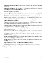
Страница 46: ... The pressure at which replenishing fluid is forced into a fluid power system Charge Relief Valve A pressure control valve whose primary function is to limit pressure in the charge circuit Check Valve A valve whose primary function is to restrict flow in one direction Closed Loop A sealed and uninterrupted circulating path for fluid flow from the pump to the motor and back Decay Rate The ratio of ...

Страница 47: ...p frequently achieved by pressurizing the fluid in the inlet line Purging The act of replacing air with fluid in a fluid power system by forcing fluid into all of the components and allowing the air a path of escape Rated Flow The maximum flow that the power supply system is capable of maintaining at a specific operating pressure Scoring Scratches in the direction of motion of mechanical parts cau...

Страница 48: ... 2008 HYDRO GEAR Printed in U S A Rev P1 ...

Отзывы: