34
-1500/-1700 IHT
MOTOR/CENTER SECTION/
PUMP ASSEMBLY
Refer to Figures 26 and 27, (next pages).
NOTE: Brake Assembly, Charge Pump
Assembly, Differential Assembly, and
Low er Hous ing/Fil ter/Man i fold As sem bly
have to be re moved before the fol low ing
steps can be per formed.
DISASSEMBLY
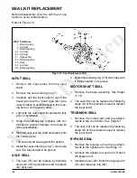
1. Remove the motor shaft assembly which
consists of the washer (82), snap ring (83),
wash er (82), 16T pin ion gear (28), spacer
(27), and shaft (24).
2. Remove motor thrust bearing re tain er
(57).
3. Remove the three screws (44) from center
section as sem bly (3).
4. Lift center section assembly (3) and motor
block assembly (21) out of main housing
(1).
5. Remove each piston (23), spring (18), and
piston seat (22) from the 21cc motor cylinder
block assembly.
6. Remove motor thrust bear ing (25).
7. Remove bypass plate (38) from center sec-
tion assembly (3).
8. Remove the two center section assembly
pins (43).
9. Remove bypass actuator (39) from the cen-
ter section (3).
10. Remove 10cc pump cylinder block as sem bly
(15).
11. Remove each piston (17), spring (18), pis ton
seat (16) from the 10cc pump cylinder block
as sem bly (21).
12. Remove block spring (14), and block thrust
washer (13) from shaft (12, Figure 19).
13. Remove the input shaft if not already re-
moved. See page 25.
INSPECTION
1. Inspect running surface of thrust bearing
(25) for ex ces sive wear.
2. Inspect each piston (23), spring (18), and
pis ton seat (22) in the mo tor cylinder block
as sem bly.
3. Inspect seal lands of the 21cc motor cyl-
in der block as sem bly (21) for excessive
wear (groov ing or smearing).
4. Inspect the two running surfaces of center
section as sem bly (3) for excessive wear
(groov ing or smearing). Abnormal wear
pat terns will usually be visible. Any wear
de tect able when a
fi
ngernail is dragged
across the surface is cause for rejection.
5. Inspect each piston (17), spring (18), pis-
ton seat (16) in the pump cylinder block
as sem bly.
6. Inspect seal lands of 10cc pump cylinder
block assembly (15) for excessive wear
(groov ing or smearing).
ASSEMBLY
1. Install input shaft assembly (12, Figure
19).
2. In
stall pump cyl in der block thrust washer
(13) and spring (14) onto in put shaft as-
sem bly (12, Figure 19).
3. Install piston washers (18), springs (17), and
pistons (18) in to the pump cylinder block
(15).
4. Install pump cylinder block assembly (15)
onto the input shaft (12). Be sure spring
ten sion is even around the entire block. To
as sist in cylinder block installation, a rubber
band can be placed around all of the pistons
to hold them in position. After the cylinder
block is installed, cut the rubber band and
remove it from the the housing.
5. Install the two center section assembly pins
(43).
6. Install the bypass actuator (39) into the
cen ter section (3).
Содержание 310-1500
Страница 7: ... 1500 1700 IHT 5 HYDRAULIC SCHEMATIC Figure 5 1700 Hydraulic Flow Illustration ...
Страница 8: ...6 1500 1700 IHT EXTERNAL FEATURES 1500 AND 1700 ...
Страница 42: ...40 1500 1700 IHT Figure 31 IHT 1500 Exploded View ...
Страница 44: ...42 1500 1700 IHT Figure 32 IHT 1700 Exploded View ...
Страница 48: ... 2008 HYDRO GEAR Printed in U S A Rev P1 ...


