Installation and Maintenance Manual
12
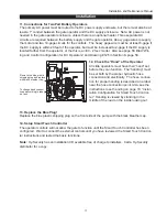
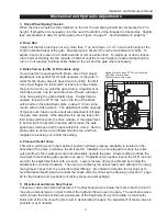
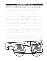
OFF
POWER
ON
Remove the blue plastic
shipping plug and replace
with black breather cap.
To change hand connect
hoses according to label
on tank.
Installation
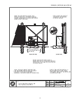
11. Connections for Two Part Battery Operators
The primary AC power must be routed to the DC power supply enclosure, but there must also be at
least a 1" conduit between the gate operator and the DC supply enclosure. Note: AC power is not
needed in the gate operator enclosure, unless there is an optional heater. Three separate DC
circuits are required between the battery supply and the gate operator. Heavy gage wires to supply
the motor and two 14-gage circuits for the controls. The heavy gage wire must be at least 6-gage if
the DC supply is within 20 feet of the operator, but must be increased to 2-gage if the DC supply is
located farther from the operator, or the this is an EX - 2'/sec model. Also see page 56 titled “Wir-
ing and Control Configuration for DC Operators” and Drawing E125 in Section 8, page 58.
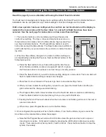
12. Check the “Hand” of the Operator
All slide operators must have their “hand” set
before they can function. The “handing” must
be set both by the proper hydraulic hose
connection and electrically. The hose connec-
tion for proper handing is described on a label
near the hose connection point. Also, see the
instructions to set handing on page 18 “Instal-
lation Configuration for Smart Touch Control-
ler.” Handing is viewed by standing in the
middle of the road on the inside looking out.
13. Replace the Blue Plug!
Replace the blue plastic shipping plug on the front side of the pump with the black breather cap.
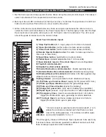
14. Setup Smart Touch Controller
The operator controls will not allow the gate to function until the Smart Touch Controller has been
configured. Wait to connect the external controls until you have reviewed the Smart Touch Control-
ler instructions and tested the basic functions.
Note: Hy-Security has an installation CD available free of charge to installers. Call a Hy-Security
distributor for a copy.


